



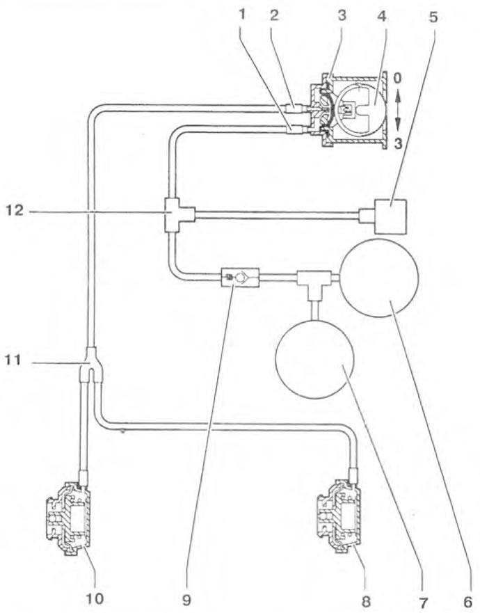
Figure 9.40. Pneumatic diagram of the headlight range adjuster: 1,2- Vacuum connections; 3 - Headlight angle adjuster; 4 - Headlight range adjustment wheel; 5 - Intake manifold (gasoline engines) or exhaust pipe (diesel engines); 6 - Brake booster: 7 - Vacuum reservoir (only on diesel engines): 8 - Headlight range control drive (left headlight); 9 - Check valve (only on diesel engines); 10 - Headlight range adjustment control drive (right headlight); 11, 12 - Connectors (only on diesel engines).
Checking the adjustment level
1. Start the engine and turn on the headlights.
2. Rotate the adjusting wheel of the regulator from position O to position 3. The dark zone of the headlights should move on the monitor from zone A to zone B (figure 9.41).
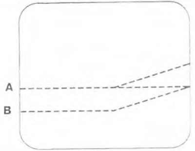
Figure 9.41. Rotate the adjusting wheel of the regulator from position 0 to position 3. The dark zone of the headlights should move on the monitor from zone A to zone B.
Checking the vacuum pressure value
The original text can be found at (VWMANUAL.ru)
3. Remove the headlight.
4. Connect vacuum tube 1 to the VAG 1368 vacuum tester (figure 9.36).
5. Start the engine and turn on the headlights.
6. Rotate the regulator adjustment wheel from position 0 to position 3. Compare the vacuum pressure value on the tester with the required one.
- Position 0 - 500 + 50 bar.
- Position 1 - 400±50 bar.
- Position 2 - 300±50 bar.
- Position 3 -100 + 50 bar.
Visitor comments