



Contents: Removal ↓ Installation ↓
Removal
1. Remove the speaker panel 1 and unscrew the screw (arrow) (figure 9.13).
Figure 9.13. Remove speaker panel 1 and unscrew the screw (arrow).
2. Remove the radio.
3. Remove panel 1 and unscrew the screw (arrow) (figure 9.14).
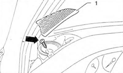
Figure 9.14. Remove panel 1 and unscrew the screw (arrow).
4. Remove regulators 2 and unscrew nuts 1 (figure 9.15).
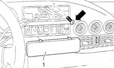
Figure 9.15. Remove regulators 2 and unscrew nuts 1.
5. Unscrew the screws (arrows) (figure 9.16).
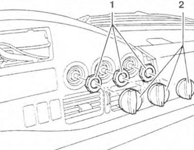
Figure 9.16. Unscrew the screws (arrows).
6. Disconnect the fog light switch 4 and remove it (figure 9.17). Mark vacuum lines 2 and 3 and disconnect them. Disconnect connector 1 from the switch.
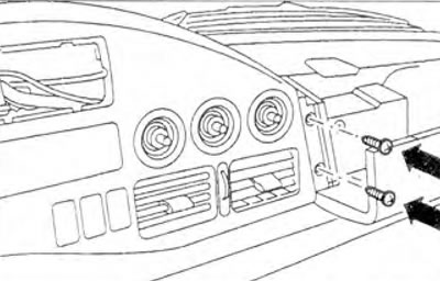
Figure 9.17. Disconnect fog light switch 4 and remove it.
Mark vacuum lines 2 and 3 and disconnect them. Disconnect connector 1 from the switch.
7. Unscrew the screws (arrows) (figure 9.18).
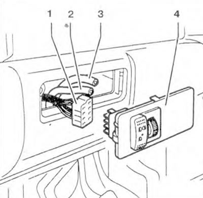
Figure 9.18. Unscrew the screws (arrows).
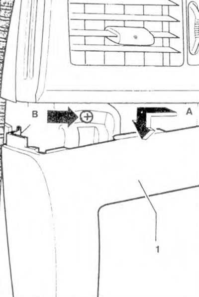
8. Remove panel 1 and lower it down (arrow A) (figure 9.19). Unscrew screws B.
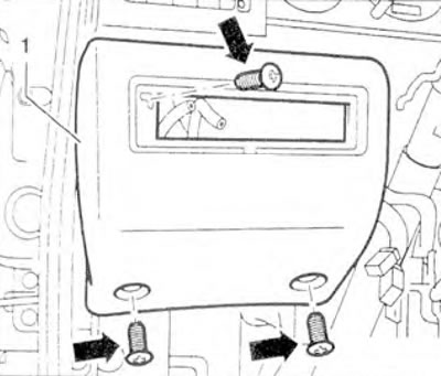
Figure 9.19. Remove panel 1 and lower it down (arrow A). Unscrew screws B.
9. Detach panel 1 from the top and move it back (figure 9.20). Disconnect the connectors from all switches. Remove panel 1.
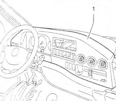
Figure 9.20. Detach panel 1 from the top and move it to the back.
10. Unscrew the screws on the left and right (arrows) (figure 9.21).
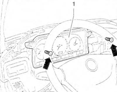
Figure 9.21. Remove the screws on the left and right (arrows).
11. Disconnect connectors 1 and 2 by pressing on the fastening tabs (arrow A) and move the retainer 3 upwards (arrow B) (figure 9.22).
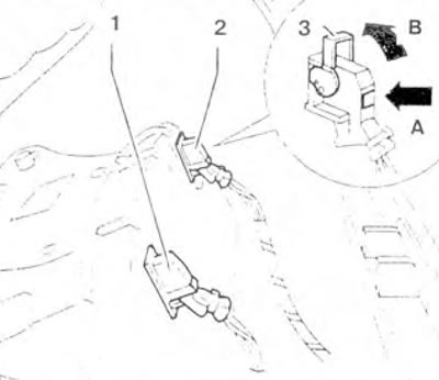
Figure 9.22. Disconnect connectors 1 and 2 by pressing on the fastening ears (arrow A) and move the retainer 3 upwards (arrow B).
12. Remove the instrument cluster from the instrument panel.
Installation
13. Installation is carried out in the reverse order of removal.
Visitor comments