



Control panel and cables
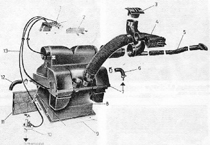
Figure 2.6. Heater parts: 1 - Heater control lever; 2 - Heater control panel; 3 - Ventilation grille for air outlet; 4 - Ventilation grille for air outlet; 5 - Air supply channel to the window; 6 - Water hose; 7 - Upper section of the air collector; 8 - Lower section of the air collector; 9 - Gasket; 10 - Cooling system control valve; 11 - Ventilation grille for air outlet; 12 - Water hose; 13 - Control cables.
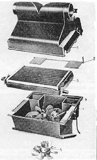
Figure 2.7. Heater disassembled: 1 - Upper section of the air collector; 2 - Air flow control flap; 3 - Heater core; 4 - Lower section of the air collector; 5 - Blower electric motor.
1. Remove the handles from the levers on the control panel. Remove the handle from the blower switch.
2. Remove the control panel by squeezing the locking tabs located behind it and pulling the panel out of the dashboard. Disconnect the wires.
3. Loosen the control cable clamps (see photo).
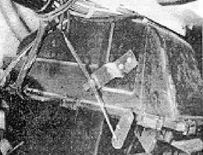
Photo 10.3. Heater control cable with clamp.
4. Remove the 2 screws securing the lever support bracket.
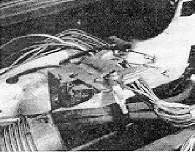
Photo 10.4. Heater control levers.
5. Disconnect the ends of the cables from the heater control levers and the damper levers and pull the cables out of the rubber bushings.
6. The heater is installed in reverse order. Secure the cables with clamps, move the heater control levers to the "off" position, and the heater flap levers and the cooling system valve to the closed position.
Blower motor
7. Working under the dashboard, loosen the spring clamps securing the upper section of the air collector to the lower one.
8. Lower the unit so that the wires can be disconnected from the motor terminals.
9. Remove the blower motor from the air collector.
10. Installation of the electric motor is carried out in reverse order.
Heater core
11. The core can only be removed after removing the heater itself.
12. Working under the dashboard, disconnect the air ducts from the pipes on the heater casing.
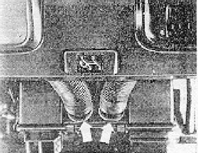
Figure 2.8. Air ducts connected to the upper section of the air collector.
13. Drain the coolant (see section 2). Disconnect the water hoses from the heater (see photo).
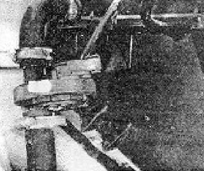
Photo 10.13. Cooling system control valve.
14. Disconnect the control cables as described above. Disconnect the blower motor electrical connector and wires from its switch.
15. Loosen the heater housing mounting screws and remove the heater assembly. Be careful not to spill coolant on the cabin floor (see photo).
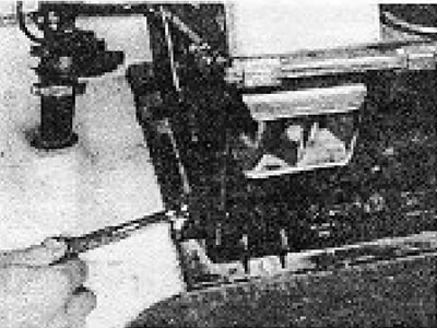
Photo 10.15. Removing the heater mounting bolt.
18. Remove the heater, release the spring clips that secure the heater sections to each other and remove the top section and pull out the core.
17. If the core becomes clogged, it must be backwashed with cold water under pressure. If the core leaks, it should be replaced or taken to a professional for repair.
18. Installation of the heater core is carried out in reverse order.
19. Connect the control cables as indicated earlier and fill the cooling system with fluid.
Visitor comments