



9. Disconnect the large inlet hose from the thermostat housing (see photo).
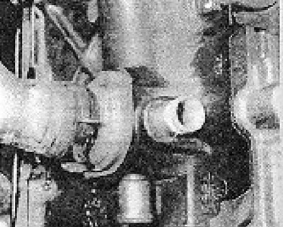
Photo 5.9. Locations of hose connections to the thermostat housing.
Note: In the attached photo, all hoses are disconnected from the thermostat housing, as the photo was taken on an engine that was removed from the car.
10. Remove the thermostat cover (see photo).
[The original information is posted on the website: www.VWmanual.ru]
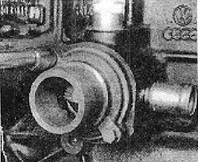
Photo 5.10. Removing the thermostat cover.
11. Remove the thermostat.
12. Check the operation of the thermostat as described in chapter 2, but based on the data specified in Specifications at the beginning of this Appendix.
13. When installing the thermostat, make sure that it has a rubber sealing ring (see photo)
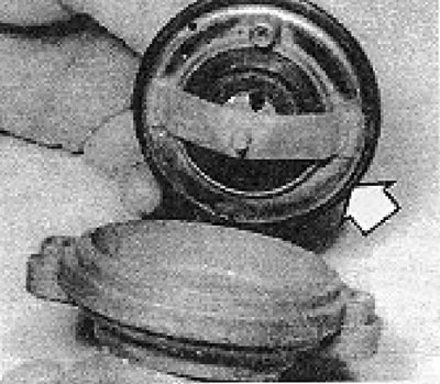
Photo 5.13A. Rubber sealing ring (shown by the arrow).
and so that the air release valve is at the top (see photo).
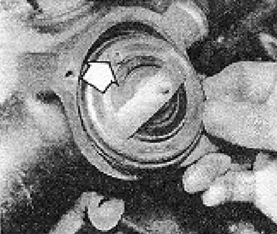
Photo 5.13B. Thermostat bleed valve (shown by the arrow).
14. Replace the cover, connect the hose(s), add fluid to the cooling system and bleed it.
Visitor comments