
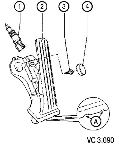
List of assemblies and parts of the accelerator pedal module for drawing VC3.090:
1. Connector black, 6-pin.
2. Accelerator pedal position sensor (G79):
- not regulated;
- the accelerator pedal position sensor transmits to the engine control unit data on the desired engine power;
- to remove, unlock with a puller;
- (A) puller slots.
3. Screw: 10 Nm.
4. Cap.
Removing
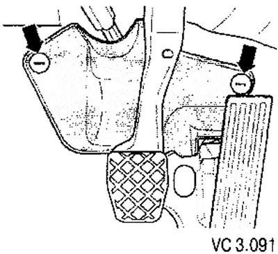
1. Before removing the accelerator pedal module, remove the trim in the footwell. unscrewing the plastic nuts for this (arrows).
2. Use a screwdriver to pry and remove the cap.
3. Remove the screw.
4. Unlock the accelerator pedal module.
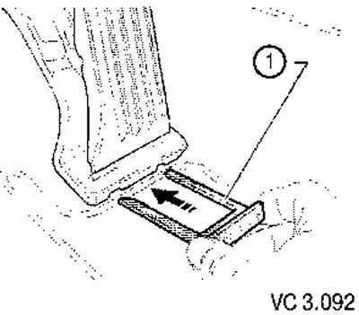
5. To remove the accelerator pedal module, insert a puller into the holes provided for this (1).
6. Disconnect the electrical connector and disconnect the wire harness guide on the accelerator pedal module.
Installation
Installation is carried out in the reverse order, while it is necessary to perform the following steps.
1. Connect the wire harness guide (1) and electrical connector (2) to the accelerator pedal module. By pressing the module, fix it on the mounting pins (8).
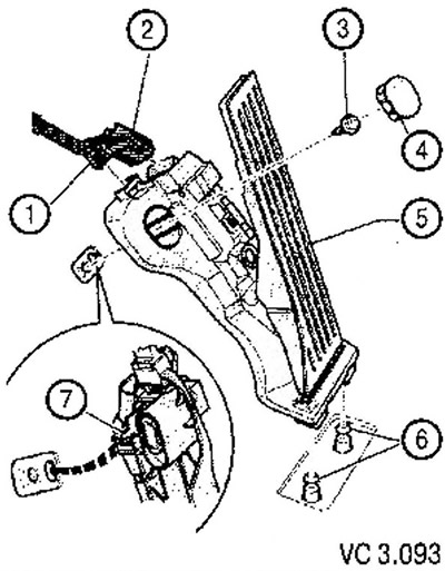
2. Install pin (7) into the hole in the floor.
3. Fix the accelerator pedal module with the screw (1), tightening torque: 10 Nm.
4. Install the cap (1).
5. Install the steering column pad.
Visitor comments