



Removal vacuum booster on a car with ABS system, carry out in the following order:
- remove the "-" wire from the battery terminal;
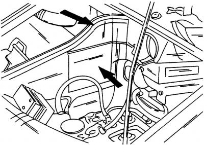
Fig. 328. AB compartment partitions (shown by arrows)
- remove the battery compartment partitions (Fig. 328);
- remove the sound insulation in the engine compartment;
- remove AB;
- remove the expansion tank of the cooling system;
- disconnect the multi-pin connector block of the coolant temperature indicator and unscrew the two bolts;
- unscrew the two bolts and remove the right partition of the battery compartment;
- unscrew one bolt and remove the left rear partition of the battery compartment. Set the expansion tank aside;
- disconnect the plug connector on the brake fluid reservoir cap and unscrew the reservoir cap;
- remove the spring clamp and disconnect the multi-contact connector block from the ABS ECU;
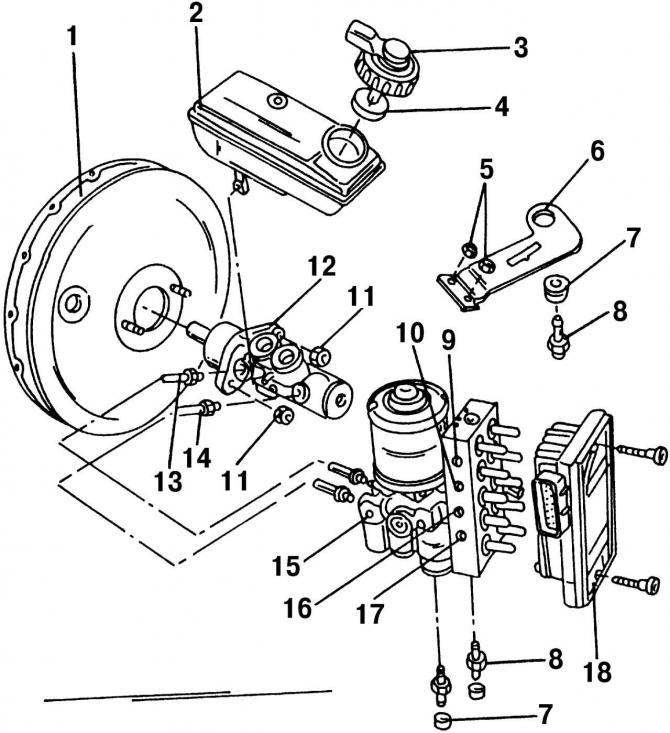
Fig. 332. Layout of parts with ABS installed: 1 - vacuum booster brake drive; 2 - tank; 3 - reservoir cover with terminals of the brake fluid emergency level sensor; 4 - float; 5 - nuts, 8 Nm; 6 - holder; 7 - rubber damper; 8 - bolt, 8 Nm; 9 - location of connection of the left front wheel brake pipe to the hydraulic unit; 10 - connection point of the brake pipe of the right rear wheel to the hydraulic unit; 11 - self-locking nut, 25 Nm; 12 - master brake cylinder; 13 - pipeline of the circuit "left front - right rear brakes" from the main brake drive to the hydraulic unit; 14 - pipeline of the circuit "right front - left rear brakes" from the main brake cylinder to the hydraulic unit; 15 - hydraulic unit; 16 - location of connection of the brake pipe of the left rear wheel to the hydraulic unit; 17 - connection point of the brake pipe of the right front wheel to the hydraulic unit; 18 - ECU–ABS
- mark with tape (on which the numbers are written) and disconnect brake pipes 9, 10, 16 and 17 of the front and rear wheels from the hydraulic unit 15 (Fig. 332);
- close the openings near the pipes and the hydraulic unit to prevent fluid leakage and dust and dirt from getting into them;
- unscrew the mounting bolts and remove the hydraulic unit together with the ABS ECU by moving it upwards;
- using a siphon bulb, pump out the brake fluid from the reservoir and remove the master brake cylinder;
- disconnect the vacuum hose going to the brake booster;
- remove the lower instrument panel cover on the driver's side;
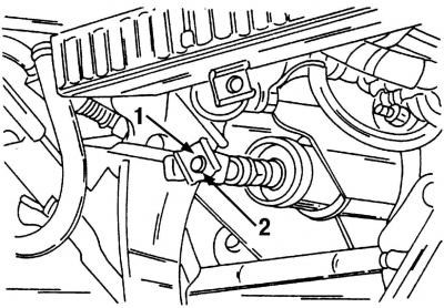
Fig. 329. Disconnecting the brake booster rod from the brake pedal: 1 - spring clamp; 2 - connecting finger
(The original can be found at: «VWManual.ru»)
- remove spring clamp 1 (Fig. 329), then remove connecting pin 2 and disconnect the brake booster push rod from the brake pedal;
- unscrew the four nuts securing the brake booster and remove it.
Installation vacuum booster, carry out in the reverse order of removal.
Visitor comments