



Figure 8.27. Parking brake system drive lever: 1 - Decorative cover; 2 - Finger; 3 - Casing; 4 - Parking brake system drive lever; 5 - Switch; 6 - Wire for the parking brake system indicator light; 7.9 - Bolts: 8 - Front drive cable; 10 - Mounting plate.
Removal
1. Raise the car.
2. Loosen bolt 1 and turn the cam in the direction of the arrow until it stops (figure 8.28).
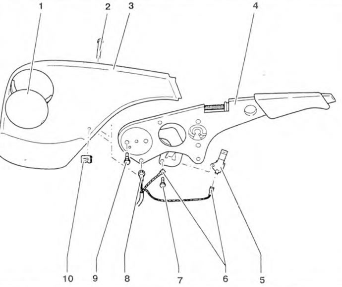
Figure 8.28. Loosen bolt 1 and turn the cam in the direction of the arrow until it stops.
3. Loosen the bolts (arrows) and move the sliding support bracket forward (figure 8.29).
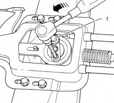
Figure 8.29. Loosen the bolts (arrows) and move the sliding support bracket forward.
4. Disconnect the lever (arrow) to which the front cable is attached from the tension sleeve (figure 8.30).
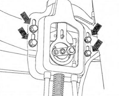
Figure 8.30. Unhook the lever (arrow) to which the front cable is attached from the tension sleeve.
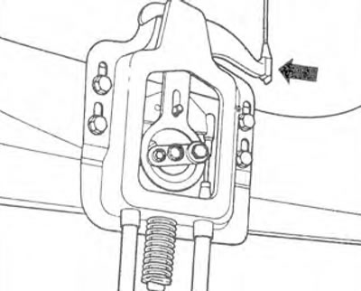
Figure 8.31. Remove mounting plate 1 and pull out pin 2.
6. Remove the cover.
7. Unscrew bolts 2 on lever 1 (figure 8.32). Disconnect the wiring connector for the indicator light. Remove the cover and disconnect the cable from the lever.
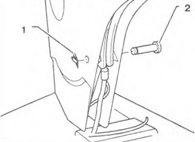
Figure 8.32. Unscrew bolts 2 on lever 1.
Installation
8. Installation is carried out in the reverse order of removal.
Adjustment
9. Loosen the parking brake lever.
10. Loosen bolt 1 and turn the cam in the direction of the arrow until it stops (figure 8.28).
11. Loosen the bolts (arrows) and move the sliding support bracket forward (figure 8.29).
12. Insert a 6 mm B key between lever 1 and support bracket 2 (figure 8.33). Move the bracket back so that lever 1 is aligned with the key in
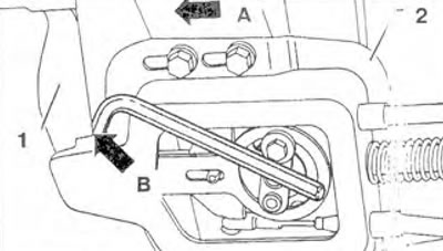
Figure 8.33. Insert 6 mm key B between lever 1 and support bracket 2. Move the bracket back so that lever 1 is aligned with key B.
13. Pull the cam in the direction of the arrow and tighten bolt 1 (figure 8.34).
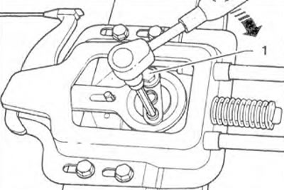
Figure 8.34. Pull the cam in the direction of the arrow and tighten bolt 1.
14. Loosen the parking brake lever and check that the wheels rotate easily.
Visitor comments