



Contents: Columns ↓ Installing a radio receiver ↓ Interference ↓ Terminal markings ↓ Radio interference suppression -…↓
Columns
The speakers must match the output characteristics of the radio receiver, especially in terms of impedance. The transistors used in the speakers are sensitive to the load applied to them.
Before choosing a location to install the speakers, check if there are any standard places for them in the car. Speakers installed in doors provide a good stereo effect, but in some cases the design of the doors does not allow for the installation of speakers in them. Another good place to install speakers is the rear shelf. Depending on the design, the speakers can be placed on it or installed cut-in.
To install the speakers and doors, you must first remove the interior door trim, which is often held in place with push pins, and then select a suitable location in the doors for the speakers.
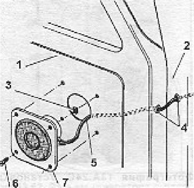
Figure 13.64. Installing speakers in the door (section 13B): 1 - Door trim; 2 - Door post; 3 - Flat stud nut; 4 - Rubber bushings; 5 - Hole cut in the door trim; 6 - Screw; 7 - Knee with a grate.
Check that the speakers do not interfere with the normal operation of the window lift. After marking the location for the column, drill holes for the screws. The speaker wires are routed through the door and door frame. If necessary, you can drill 10mm diameter holes for them and install rubber bushings in them. Don't forget about the waterproof caps that usually come with the speakers.
Installing speakers on the rear shelf is a little easier, but you need to find a precise location for them. Remember that to achieve a good stereo effect, your knees should be as far apart as possible. Sometimes you can achieve a good effect by reflecting the sound off the rear window.
Installing a radio receiver
Most models initially have a place for installing a radio receiver on the dashboard or center console (standard opening dimensions are 189.5 mm x 60 mm). If there is no special hole, you can install the radio under a shelf for small items, but in this case it will have to be grounded using a special wire. There are special "boxes" for installing a radio receiver on sale, which have three walls.
The antenna is connected using a standard plug located at the end of the antenna wire.
Note: It is best to disconnect the battery ground cable during radio installation. Before connecting the receiver to the vehicle's electrical system, check the polarity. Most models are equipped with a negative ground, but many receivers/car radios have a universal plug that allows them to be connected to systems with either negative or positive ground. Incorrect connection can have serious consequences.
The supply wire is usually already connected to the receiver and has half of an in-line fuse holder at its end. The other half of the holder with a suitable 3A or 5A fuse is located at the end of the cord that should be connected to the vehicle's electrical system. The cord can be connected to a special terminal on the ignition switch. In this case, the receiver will operate when the ignition is turned on or when the ignition key is in the "auxiliary" position. Power to the receiver will be cut off when the key is removed from the ignition. If you connect the cord to any of the terminals in the fuse box, the receiver will still work when the ignition is off, and you will have to turn it off every time you leave the car.
Before testing the receiver, check that the speakers are connected, as operating without a load can damage the output transistors.
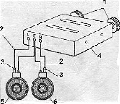
Figure 13.65. Typical speaker connection diagram (section 13B): 1 - Control handles; 2 - Colored wire; 3 - Marked terminal; 4 - Radio/car radio; 5 - Left column; 6 - Right column.
Check the receiver operation on all ranges. The antenna trimmer must be adjusted to achieve good reception of a weak signal on medium waves (somewhere along the length of 200 m).
Interference
As a rule, when the electric current changes suddenly, unwanted noise occurs. The machine contains many devices whose task is to sharply change the current (for example, a contact breaker).
When current pulsates in the spark plugs, noise is also generated, which will inevitably be received by the radio receiver unless measures are taken to suppress it.
Interference reaches the radio receiver in two ways:
- Through the wiring;
- Through radiation received by the antenna.
Before you begin checking, make sure the hood is latched and the radio is well grounded (not through the outer conductor of the antenna), there are no working fluorescent lamps near the vehicle, the antenna trimmer is adjusted and there are no obstacles to signal reception (the car is not parked in a metal garage).
Turn on the radio and tune to the middle part of the medium wave (MW) range, where there are no transmitting stations. Increase the volume and turn on the ignition (but do not start the engine). Check for any irregular clicking or "white noise." Simply tapping the dashboard can also cause "white noise." The source of this noise is the voltage regulator, located behind the dashboard and often mounted near the speedometer. To eliminate noise, it is necessary to install a capacitor, and in difficult cases, also chokes on the power wires.
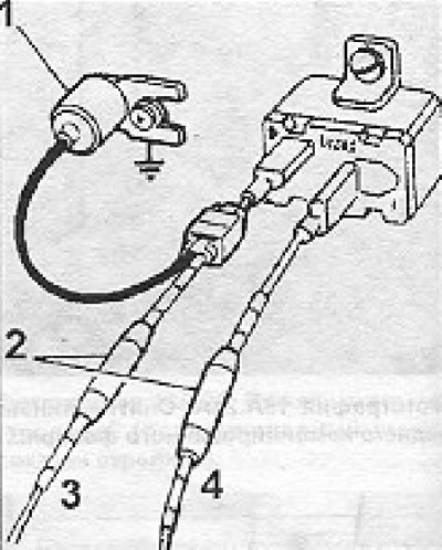
Figure 13.66. Suppression of interference from a voltage stabilizer (section 13B): 1 - Capacitor; 2 - Chokes; 3 - Power cord; 4 - To the devices.
Start the engine and check for medium wave interference. Depending on the type of interference, they may have the following sources.
A dry crackling noise that suddenly disappears when the engine speed is reduced or when the headlights are turned on can be caused by the voltage regulator.
The howling sounds, the pitch of which changes depending on the engine speed, are caused by the generator. Try temporarily removing the fan belt - if the noise disappears, then the generator really was the source.
Regular clicking sounds, the frequency of which varies depending on engine speed, are caused by the ignition system. Check to see if the interference is coming through the wires or through the antenna. To do this, you need to disconnect the antenna (and it is better to short-circuit its input jack or connect a 62 picofarad capacitor to it). If the noise stops, it is coming through the antenna; if not, it is coming through the wiring.
Noise from windshield wipers, washers, blowers, turn signals, brake lights, etc. usually travels to the receiver through the wiring and can be eliminated using capacitors and chokes. To test, turn on each of these devices one by one and monitor the noise with the antenna connected and disconnected. Some models are equipped with electric fuel pumps, which cause noise in the form of an irregular clicking sound, which is very common when the ignition is turned on without starting the engine. A running electric pump may also produce noise such as howling or crackling.
Keep in mind that if almost all of the vehicle's electrical equipment is causing some kind of interference, the cause is most likely poor antenna grounding.
Terminal markings
Below we will often refer to the markings of certain terminals. Depending on the manufacturer, the terminals may be marked differently. If in doubt, please refer to the table below for the most common markings.
| Generator | Generator terminal (thick wire) | Excitation winding terminal |
| DIN/Bosch | B+ | DF |
| Delco Remy | + | EHS |
| Ducellier | + | EHS |
| Ford (USA) | + | DF |
| Lucas | + | F |
| Marelli | +B | F |
| Ignition coil | Ignition switch terminal | Contact breaker terminal |
| DIN/Bosch | 15 | 1 |
| Delco Remy | + | - |
| Duccellier | VAT | RUP |
| Ford (USA) | B/+ | SV/- |
| Lucas | SW/+ | - |
| Marelli | BAT/+B | D |
| Voltage regulator | Voltage supply terminal | Excitation winding terminal |
| DIN.Bosch | B+/D+ | DF |
| Delco Remy | VAT/+ | EHS |
| Ducellier | WWII/WAT | EHS |
| Ford (USA) | VAT | DF |
| Lucas | +/A | F |
| Marelli | F |
Radio Interference Suppression - Ignition
All models are equipped with ignition cables with built-in radio interference suppression. You can replace these wires with regular ones only if you install special resistive caps on the spark plugs, which will take on the function of suppressing radio interference. However, it should be noted that in the VHF range these caps are ineffective compared to resistive ignition wires (with built-in radio interference suppression). To check which wires are on your car, you should measure the resistance of each wire with an ohmmeter - in the case of wires with built-in radio interference suppression, it should be equal to 5000-10000 ohms.
As another measure to suppress interference from the ignition system, you can install a 1 microfarad capacitor between the low-voltage side of the ignition coil and ground. Never connect the capacitor to the coil terminal designated for the contact breaker, as this will result in the breaker contacts burning out in no time.
If, despite all measures taken, the noise does not disappear, perform the following operations:
- Check ignition coil grounding, clean paint from retaining clip.
- If this does not help, lift the hood. If the noise pattern does not change, this may indicate that the hood is not electrically connected to the car body. In this case, the hood cover should be connected to the body using a branded braided busbar. If the noise increases when the hood is raised, spark plug wires with higher specific linear resistance (Ohm/m) should be installed.
- If this does not help, then it is possible that secondary radiation from metal parts is occurring. Using a braided bus bar, systematically check the grounding in the following locations:
- between the engine and the body,
- exhaust system and body,
- front suspension and engine,
- steering column and body (especially Italian and French cars),
- gear lever and engine and gear lever and body (again, especially Italian and French cars),
- metal rear shelf and body.
- Once you have located the part that is responsible for the secondary radiation, you should permanently ground it using a braided busbar.
- As a next step, you can try installing radio interference suppressors on each ignition wire on the distributor side.
- Further occurrence of radio interference is unlikely to be required, given the class of automotive radio equipment.
Electronic ignition systems have built-in radio interference suppression, but this does not eliminate the need for special resistive spark plug wires. In some cases (but not always) you can install a capacitor on the low voltage supply side of the ignition coil. In all cases, strictly follow the manufacturer's instructions, as you can easily damage the system's semiconductors.
Radio interference suppression generator
For older models with a DC generator, generator noise can be eliminated with a 1 µF capacitor connected between the "D" (large) terminal and ground. For an AC generator, connect a 3 microfarad capacitor between the B+ terminal (thick wire) and "ground." Additional interference suppression can be achieved by using a filter installed on the power cable to the radio receiver.
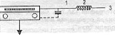
Figure 13.67. Radio interference suppressor installed on the power line of a radio receiver (section 13B): 1 - Electrolytic capacitor 1000 μF. 16 V; 2 - Throttle; 3 - 12V power supply.
It is essential that:
- Capacitors should never be connected to the generator excitation winding terminals;
- The generator would not turn on if it was disconnected from the battery.
Radio interference suppression - voltage regulator
Interference from voltage regulators used with DC generators is removed using a 1 µF capacitor connected between the "D" terminal of the control unit and ground.
Voltage regulators used with alternators come in three types:
- a) Regulators with vibration contact, located separately from the generator;
- b) Electronic regulators located separately from the generator;
- c) Electron built-in regulators.
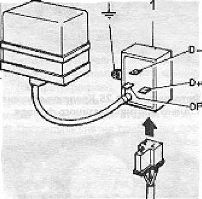
Figure 13.68. Typical filter used for a vibration contact voltage regulator (section 13B): 1 - Filter.
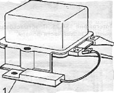
Figure 13.69. Suppression of radio interference caused by a voltage regulator with a vibration contact on amplitude-modulated (AM) transmissions (section 13B): 1 - Capacitor.
In the case of type (a) regulators, interference may occur with frequency (FM) and amplitude (AM) modulated transmissions (VHF).
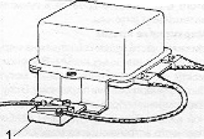
Figure 13.70. Suppression of radio interference caused by a voltage regulator with a vibrating contact on frequency modulated (FM) transmissions (section 13B): 1 - Capacitor.
For some car models, controllers with built-in radio interference suppression are produced. In other cases, you can use filters. Alternatively, you can suppress noise on amplitude modulated transmissions by installing a 2 or 3 microfarad capacitor on the D- or B+ terminal of the voltage regulator. Interference on frequency modulated transmissions can be eliminated by using a 2 or 3 microfarad pass-through capacitor.
Electronic voltage regulators generally do not cause interference, but if problems occur, installing a 1 μF capacitor between the regulator's "+" terminal and ground may help.
Built-in electronic voltage regulators also rarely cause interference. If interference does occur, it is usually in combination with noise from the generator. In the case of Lucas ACR generators and their counterparts from Femsa, Delco and Bosch, the problem can be solved by installing a 1 or 2 UF capacitor between the signal lamp terminal (IND) and ground.
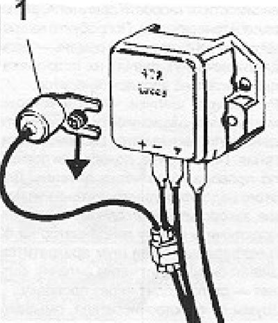
Figure 13.71. Suppression of radio interference from an electronic voltage regulator (section 13B): 1 - Capacitor/
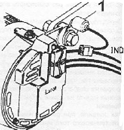
Figure 13.72. Suppression of radio interference from the built-in electronic voltage regulator (section 13B): 1 - Capacitor/
Radio interference suppression - other equipment
Windscreen wiper motor connect the engine body to the ground using a braided busbar. For all electric motors, install 7A chokes on the wires leading to the electric motor.
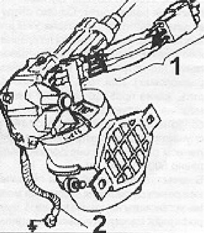
Figure 13.73. Suppression of radio interference from the windshield wiper motor (section 13B): 1 - Chokes; 2 - Grounding bus with braid.
Heater motor - install 7 A linear chokes on both wires of the electric motor. If necessary, you can connect both wires to ground via 1 μF capacitors.
Electronic tachometer — an electronic tachometer may be the cause of noise from the ignition system. You can check this by disconnecting the wire from the "CB" terminal of the ignition coil. To suppress noise, install a 3 A linear choke on the tachometer wire at the "CB" terminal of the coil.
Sound signal a combination of a capacitor and a choke will help if the audio signal is directly connected to a 12V power source. An alternative is to use a relay, which will reduce the length of the wires that carry the noise.
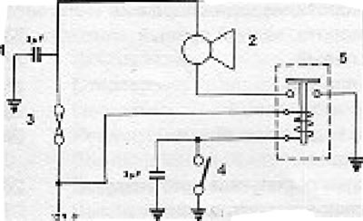
Figure 13.74. Relay used to suppress noise from an audio signal (section 13B): 1 - Feed-through capacitor; 2 - Sound signal; 3 - Additional fuse; 4 - Sound signal button; 5 - Relay.
Electrostatic noise - these noises manifest themselves in the form of crackling, which disappears in damp weather. Part of the problem is the build-up of static electricity in the driven wheels and on the car body. To remove static electricity from wheels, spring-loaded contacts can be installed to ensure good conductivity between the moving parts of the wheel and the car body. Sometimes changing the tire helps (because different tires have different resistance). In difficult cases, a rubber strip suspended from the back of the car and touching the ground helps.
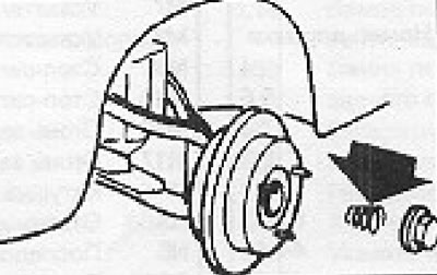
Figure 13.75. Spring-loaded contacts on wheels used for radio interference suppression (section 13B).
Fuel pump — Install a 1 μF capacitor between the pump power supply wire and ground. If this doesn't help, install a 7 Amp linear inductor on the power supply wire near the pump.
Passage of electromagnetic radiation through the receiver/car radio housing
In some cases, electromagnetic radiation from the dashboard wires can be so strong that it passes through the metal housing of the radio/car stereo.
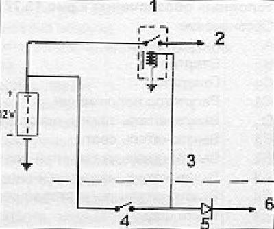
Rfig. 13.76. Ignition coil relay used to suppress interference caused by electromagnetic waves passing through the body of the radio/car radio (section 13B): 1 - Relay; 2 - To the ignition coil (terminal "15", "SW" or "+") through a ballast resistor (if installed); 3 - "Torpedo"; 4 - Ignition switch; 5 - Diode; 6 - To the generator signal lamp.
This is usually caused by a single wire passing too close and manifests itself in interference from the ignition system during amplitude-modulated transmissions and cassette playback and/or interference from the generator when playing cassettes. First of all, it is necessary to check the reliability of fastening all clips and (or) screws of the radio receiver.
The next step is to try moving the radio to a different location by installing temporary wires. If you find a place where there is little interference, leave the receiver there. If rearrangement is not possible for technical reasons, install the receiver in its old location.
Generator noise when playing tapes is caused by radiation from the main charging wire that runs from the battery to the generator output terminal, usually via the "+" terminal on the starter relay. On some cars this wire runs under the dashboard, so the solution is to find a direct route for this wire. Disconnect the wire from the generator output terminal and connect a new wire with a cross-sectional area of at least 6 mm between the generator and the battery, passing it along the shortest route. Remember that you cannot start the engine with the generator disconnected from the battery.
Interference from the ignition system can be a serious problem on amplitude-modulated transmissions and when playing cassettes. Try wrapping the interfering wire in foil near the radio or creating a deflection shield by connecting it to a good ground. Another solution is to use a relay to turn on the ignition coil. This relay should be installed near the coil, and due to it, the current from the primary winding will not get to the dashboard and will not pass through the ignition switch.
Visitor comments