



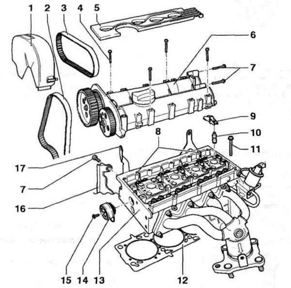
Fig. 4.8 a. Cylinder head:
1 - Upper part of the timing belt cover; 2 - Main timing belt; 3 - Auxiliary timing belt; 4, 7, 11, 15 - Bolts; 5 - High-voltage wire guide, 6 - Camshaft housing; 8 - Mounting pins; 9 - Roller rocker; 10 - Pusher; 12 - Cylinder head gasket; 13 - Cylinder head; 14 - Auxiliary timing belt tension roller; 16 - Rear timing belt cover; 17 - Lifting eye.
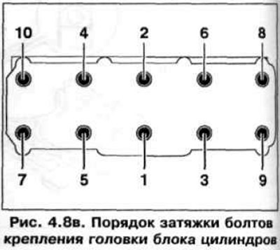
Checking the cylinder head deformation is shown in Fig. 4.8 b. The order of tightening the cylinder head mounting bolts is shown in Fig. 4.8 c. Tightening torque of the cylinder head mounting bolts; stage 1 - 40 Nm, Stage 2 - 60 Nm, Stage 3 - 90°, Stage 4 - 90°.
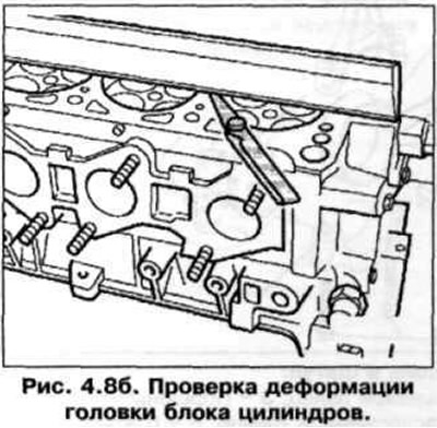
Cylinder head deformation: 0.05 mm.
Visitor comments