



Contents: Removal ↓ Installation ↓
Removal
On AGR, ALH, ASV engines
1. Disconnect the pipe between the compressed air radiator (intercooler) and the intake manifold.
For all engines
2. Remove the upper part of the timing belt cover, vacuum pump, soundproof cover, ribbed belt.
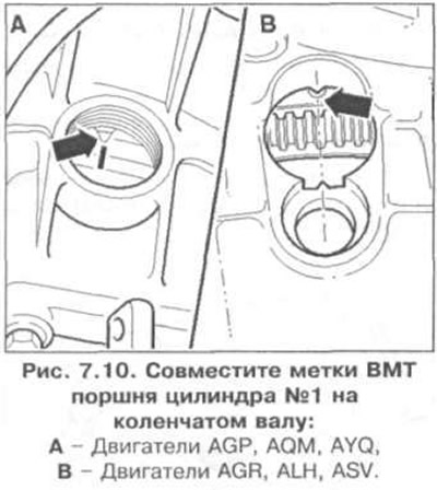
3. Align the TDC marks of the piston of cylinder No.1 on the crankshaft; A - AGP, AQM, AYQ engines, B - AGR, ALH, ASV engines (Fig. 7.10).
On engines AGP, AQM, AYQ
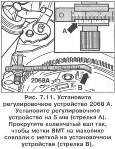
4. Install adjusting tool 2068 A as shown in Fig. 7.11. Set the adjusting tool to 5 mm (arrow A). Rotate the crankshaft so that the TDC marks on the flywheel coincide with the mark on the setting tool (arrow B).
On AGR, ALH, ASV engines
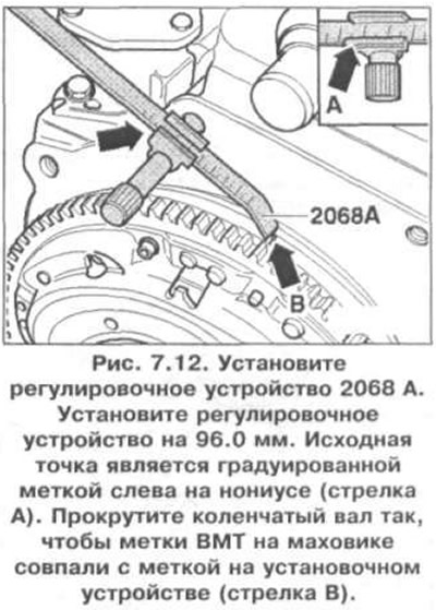
5. Install the 2068 A adjuster as shown in Fig. 7.12. Set the adjuster to 96.0 mm. The reference point is the graduated mark on the left side of the vernier (arrow A). Rotate the crankshaft until the TDC marks on the flywheel coincide with the mark on the adjuster (arrow B).
For all engines
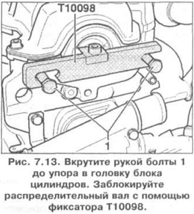
6. Screw bolts 1 into the cylinder head by hand until they stop (Fig. 7.13). Lock the camshaft using the T10098 locking tool.
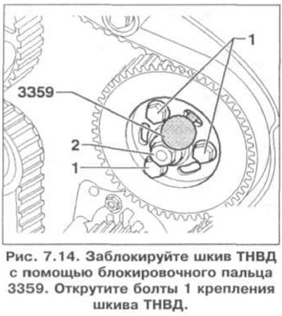
7. Lock the fuel injection pump pulley using locking pin 3359 (Fig. 7.14). Unscrew bolts 1 securing the fuel injection pump pulley.
8. Loosen the tension roller.
9. Remove the crankshaft pulley/damper.
10. Remove the lower and middle parts of the timing belt cover.
11. Mark the direction of rotation of the timing belt.
12. Remove the timing belt.
Installation
13. Make sure that the TDC mark on the flywheel and the reference point are aligned.
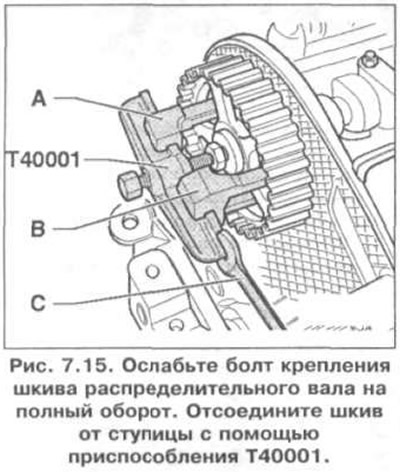
14. Loosen the camshaft pulley mounting bolt by a full turn (Fig. 7.15). Disconnect the pulley from the hub using the T40001 tool.
15. Install the timing belt on the crankshaft toothed pulley, idler pulley, fuel injection pump pulley, coolant pump pulley and tension roller in the direction of rotation.
16. Set the fuel injection pump pulley to the central position.
17. Install the camshaft pulley with the timing belt and screw in the pulley mounting bolt (the pulley can still spin).
On engines AGP, AQM, AYQ
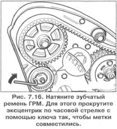
18. Tighten the timing belt (Fig. 7.16). To do this, turn the eccentric clockwise with a wrench so that the marks align.
On AGR, ALH, ASV engines
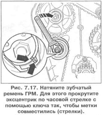
19. Tighten the timing belt (Fig. 7.17). To do this, turn the eccentric clockwise with a wrench until the marks align (arrows).
For all engines
20. Tighten the tension roller locking nut. Tightening torque: 20 Nm.
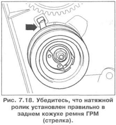
21. Make sure that the tension roller is installed correctly in the rear timing belt cover (arrow) (Fig. 7.18).
22. Check again that the TDC mark on the flywheel and the reference point are aligned.
23. Tighten the camshaft pulley mounting bolt to 45 Nm. Tighten the fuel injection pump pulley mounting bolt to 20-25 Nm.
24. Remove the camshaft pulley retainer and the fuel injection pump pulley locking pin.
25. Turn the crankshaft two revolutions in the direction of rotation so that the TDC marks on the crankshaft are aligned.
26. Check the alignment of the TDC marks on the flywheel, check the locking of the camshaft pulley using a locking device, check the locking of the fuel injection pump pulley, check the installation and ease of rotation of the tension roller.
27. If the marks are not aligned, pull the tension roller with a wrench, loosen the fastening nut, rotate the eccentric clockwise so that the marks are aligned, and tighten the nut to 45 Nm.
28. Turn the crankshaft two revolutions in the direction of rotation so that the TDC marks on the crankshaft are aligned.
29. Repeat the checks.
30. Install the timing belt cover parts, damper and cylinder head cover.
31. Install the ribbed belt.
32. Check the fuel injection pump supply.
Visitor comments