



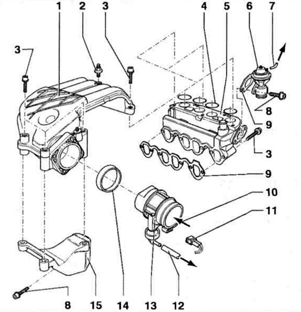
Fig. 7.9 a. Intake manifold of AGP, AQM engines:
1 - Upper part of the intake manifold; 2, 3, 8 - Bolts; 4 - Sealing ring; 5 - Lower part of the intake manifold; 6 - Exhaust gas recirculation valve (mechanical); 7 - Vacuum tube to the exhaust gas recirculation valve; 9 - Gasket; 10 - From the air filter; 11 - Wiring connector, black, two-pin, for intake manifold changeover valve; 12 - Vacuum tube to the bypass valve; 13 - Air intake manifold with intake manifold flap and intake manifold switching valve; 14 - Seal; 15 - Bracket.
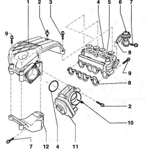
Fig. 7.9 b. Intake manifold of the AYQ engine:
1 - Upper part of the intake manifold; 2, 3, 7, 9 - Bolts; 4 - Sealing ring; 5 - Lower part of the intake manifold; 6 - Exhaust gas recirculation valve (mechanical); 8 - Gasket; 10 - To the air filter; 11 - Intake manifold flap actuator; 12 - Bracket.
(The article is published on this resource: VWMANUAL.ru)
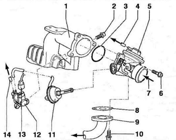
Fig. 7.9 c. Intake manifold of AGR, ALH, ASV engines:
1 - Intake manifold; 2, 6, 10 - Bolts; 3 - Sealing ring; 4 - Vacuum tube to the exhaust gas recirculation valve; 5 - Air intake manifold with intake manifold flap and exhaust gas recirculation valve; 7 - From the intercooler radiator; 8 - Gasket; 9 - Connecting pipe; 11 - Vacuum element; 12 - Intake manifold switching valve; 13 - Wiring connector, black, two-pin, for intake manifold changeover valve; 14 - Vacuum tube to the bypass valve.
Visitor comments