English Русский
Български
Беларускі
Український
Српски
Hrvatski
Română
Polski
Slovenský
Magyar
  |  Articles  |  Sitemap  |  Contacts  |    |
Car maintenance Ford Car maintenance Hyundai Car maintenance Chevrolet Car maintenance BMW Car maintenance Audi Car maintenance Opel Car maintenance AvtoVAZ
VWmanual.ru


Main   Passat   Golf   Polo   Touareg   Tiguan   Sharan   Transporter   Others  
Sharan 1 (1995-2000)

Removal and installation the clutch master cylinder (VW Sharan 1)

  • Main
  • Sharan
  • Sharan 1
  • Transmission
  • Clutch
  • Removal and installation the clutch master cylinder
            0


Due to the location of the clutch master cylinder, its removal is labor intensive, as preparatory work must be carried out to gain access to the clutch master cylinder.

Remove the clutch master cylinder in the following order:
  • disconnect the terminals from the battery and remove it. Don't forget to have the radio security code with you;
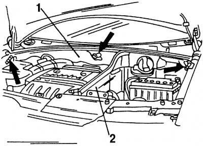
Fig. 234. Air duct and partition attachment points AB (the parts are shown in the places of…

Fig. 234. Air duct and partition attachment points AB (the parts are shown in the places of attachment by arrows): 1 - air duct; 2 - AB compartment partition

  • remove air duct 1 (Fig. 234) and partition 2 of the battery compartment;
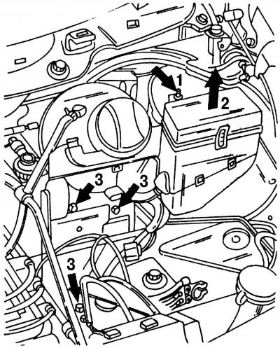
Fig. 235. Attachment points for the battery casing and the additional relay block holder

Fig. 235. Attachment points for the battery casing and the additional relay block holder

  • if installed, remove the additional relay block holder (fig. 235, arrows 1 and 2);
  • unscrew the mounting bolts (fig. 235, arrow 3) and remove the battery cover with the expansion tank of the cooling system. Put the tank aside;
  • disconnect the hose from the intake manifold. Collect the leaking fluid;
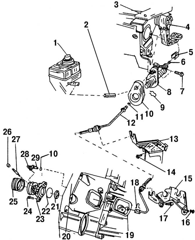
Fig. 232. Parts of the clutch hydraulic drive: 1 - tank; 2 - supply hose; 3 - pedal block; 4 -…

Fig. 232. Parts of the clutch hydraulic drive: 1 - tank; 2 - supply hose; 3 - pedal block; 4 - clutch pedal; 5 - safety holder; 6 - push rod; 7 - bolt, 20 Nm; 8 - master cylinder; 9 - locking clamp; 10 - gasket, always replaceable; 11 - O-ring; 12 - hose/pipeline; 13 - bracket; 14 - bolt, 25 Nm; 15 - bracket on gearbox; 16 - nut, 20 Nm; 17 - bolt, 20 Nm; 18 - locking clamp; 19 - dust cap; 20 - gearbox; 21 - oil seal; 22 - O-ring, always replaceable; 23 - slave cylinder with release bearing; 24 - flange bolt, 11 Nm; 25 - corrugated cover; 26 - dust cap; 27 - Air bleed screw; 28 - union nut, 20 Nm; 29 - pipeline
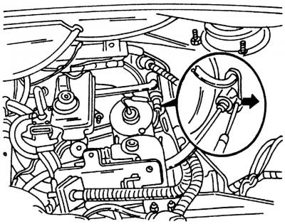


Fig. 236. Pipeline spring retaining clamp (can be pressed out with a screwdriver)

Fig. 236. Pipeline spring retaining clamp (can be pressed out with a screwdriver)

  • insert a small screwdriver under the locking clamp 9 (Fig. 232) of the pipeline and press it in the required direction (fig. 236, arrow). Disconnect the pipeline from the master cylinder and remove the O-ring 10 (Fig. 232);
  • remove the clutch pedal unit cover;

Fig. 237. Removing the clutch pedal from the push rod

Fig. 237. Removing the clutch pedal from the push rod

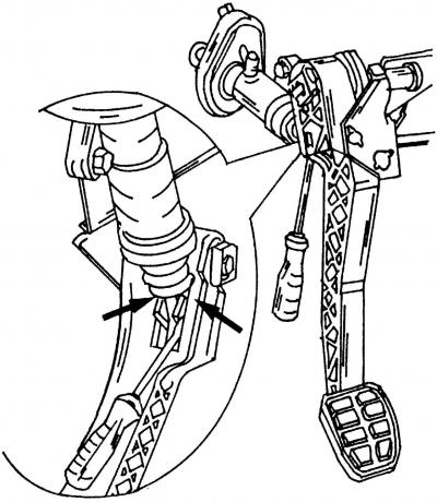
  • insert a screwdriver into the place where the clutch pedal is attached (Fig. 237) to the push rod;
  • pull the clutch pedal slightly towards the seat. Use a screwdriver to push both sides of the pedal mount inward (first one side, then the other) and disengage them;
  • remove the pedal by hitting it in the direction of the chair. If it does not come out, you can pull it out in the same direction;
  • unscrew bolt 6 (Fig. 232) and remove the clutch master cylinder.

Install the clutch master cylinder in the reverse order of removal. First, place the pushrod holder over the end of the pushrod. To secure the pushrod, press it toward the front wall until the fastener clicks into place. Move the pushrod back and forth to ensure it is properly installed.

After installing the clutch master cylinder, bleed the air from the clutch release drive hydraulic system.

This article is available at russian, bulgarian, belarusian, ukrainian, serbian, croatian, romanian, polish, slovak, hungarian
The text has been checked: Tarasov Ivan

Share information:

Пресс волл (press wall) - баннер.
Previous articles
Removal and installation the clutch slave cylinder
Clutch release drive — design description
Clutch installation
Checking the technical condition and checking the clutch
Removal the clutch
Clutch — design description
Next articles
Bleeding the Clutch Hydraulic Drive
Possible clutch malfunctions


Similar articles from other manuals for VW cars:
Removal and installation the master cylinder of the hydraulic… Passat B2 (1981-1988)
Clutch Master Cylinder — Replacement Golf 5 (2003-2008)
Brake master cylinder and brake booster Polo 3 (1995-2003)
Removal and installation the master brake cylinder Touareg 1 (2002-2006)
Removal and installation the clutch master cylinder Tiguan 1 (2007-2015)
Timing Belt Adjustment (4-Cylinder Petrol) Transporter T4 (1990-2003)
Vacuum booster and brake master cylinder LT 2D (1996-2003)
Link to this page in different formats


Visitor comments


No comments yet


How much will 49 + 49 =


Sharan 1 
  • General information
  • Introduction to guide
  • Maintenance
  • Petrol engines
  • Engine repair 2.8 l (AAA)
  • Engine repair 2.0 l (ADY)
  • Lubrication system
  • Cooling system
  • Fuel injection system
  • Ignition system
  • Diesel engines
  • Engine repair
  • Lubrication system
  • Cooling system
  • Supply system
  • Transmission
  • Clutch
  • Manual gearbox and shafts
  • Chassis
  • Steering
  • Car suspension
  • Brake system
  • Electrical equipment
  • Equipment and devices
  • Power devices
  • Electrical circuits
VWmanual.ru © 2016-2026 | Mobile version | News and articles | Sitemap: EN BG BY UA RS HR RO PL SK HU | Write message | Site search
Passat B2 • Passat B3 • Passat B4 • Passat B5 • Passat B6 • Golf 1, diesel • Golf 1, petrol • Golf 2, petrol • Golf 2 • Golf 3 • Golf 4 • Golf 5 • Polo 3 • Polo 4 • Touareg 1 • Tiguan 1 • Sharan 1 • Transporter T3 • Transporter T4 • LT 28 • LT 2D • Beetle • Caddy 3 •
Our website uses cookies to ensure functionality and convenience.