



Contact 1 - ground connection (terminal 31). Contact 3 - positive terminal (terminal 30). Contact 13 - K-wire to contact 29 of the ABS/EDL control unit wiring connector.
ABS/EDL control unit wiring connector (version 5.0) - in Figure 8.43, ABS/EDL control unit (version 5.3) - in Figure 8.44.
The assignment of the contacts of the wiring connector of the ABS/EDL control unit version 5.0 is given in Table 8.2, and for the ABS/EDL control unit version 5.3 - in Table 8.3.
Table 8.2. ABS/EDL control unit wiring connector pin assignment version 5.0
| Contact | Contact assignment |
| 1 | Ground connection on the left side of the engine compartment |
| 2 | Supply voltage from the positive battery terminal |
| 3 | |
| 4 | Supply voltage of terminal 15 |
| 5 | Not used |
| 6 | |
| 7 | |
| 8 | |
| 9 | |
| 10 | |
| 11 | |
| 12 | EDL warning light |
| 13 | Not used |
| 14 | |
| 15 | Ground connection on the left side of the engine compartment |
| 16 | Front left wheel speed sensor |
| 17 | |
| 18 | Rear left wheel speed sensor |
| 19 | |
| 20 | Rear right wheel speed sensor |
| 21 | |
| 22 | Not used |
| 23 | Front right wheel speed sensor |
| 24 | |
| 25 | Not used |
| 26 | |
| 27 | |
| 28 | Brake light switch |
| 29 | T14/13 connector, self-diagnostics |
| 30 | Not used |
| 31 | |
| 32 | |
| 33 | |
| 34 | |
| 35 | |
| 36 | |
| 37 | |
| 38 | |
| 39 | |
| 40 | ABS warning light |
Table 8.3. ABS/EDL control unit wiring connector pin assignment version 5.3
| Contact | Contact assignment |
| 1 | Rear right wheel speed sensor |
| 2 | |
| 4 | Front right wheel speed sensor |
| 5 | |
| 6 | Front left wheel speed sensor |
| 7 | |
| 8 | Rear left wheel speed sensor |
| 9 | |
| 10 | Not used |
| 11 | T14/13 connector, self-diagnostics |
| 12 | Not used |
| 13 | |
| 14 | Brake light switch |
| 15 | Relay supply voltage |
| 16 | Ground connection below the battery |
| 17 | Supply voltage from the positive battery terminal |
| 18 | |
| 19 | Ground connection below the battery |
| 20 | ABS warning light |
| 21 | Not used |
| 22 | EDL warning light |
| 23 | Not used |
| 24 | |
| 25 | |
| 26 | |
| 27 | |
| 28 | |
| 29 | |
| 30 | |
| 31 |
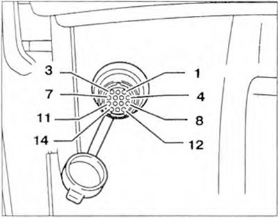
Figure 8.42. Wiring connector for ABS/EDL system self-diagnosis.
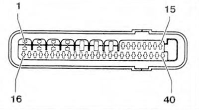
Figure 8.43. ABS/EDL control unit wiring connector (version 5.0)

Figure 8.44. ABS/EDL control unit wiring connector(version 5.3)
View the original on this portal [VWmanual.ru]
Visitor comments