



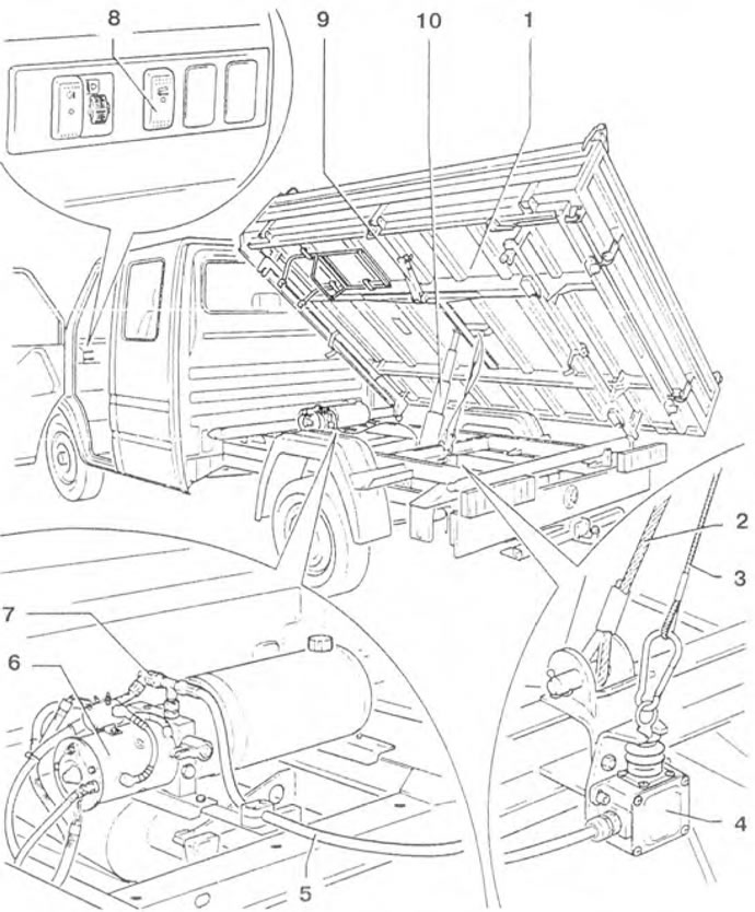
Figure 10.20. Vehicle with a three-way unloading body: 1 - Body; 2 - Safety cable; 3 - Locking cable; 4 - Limit switch (switches off the engine of the electro-hydraulic unit via a stop cable when the maximum angle of the body is reached); 5 - Oil pressure line; 6 - Electro-hydraulic unit; 7 - Pressure switch; 8 - Button with signal light; 9 - Safety bracket; 10 - Multi-piston hydraulic cylinder.
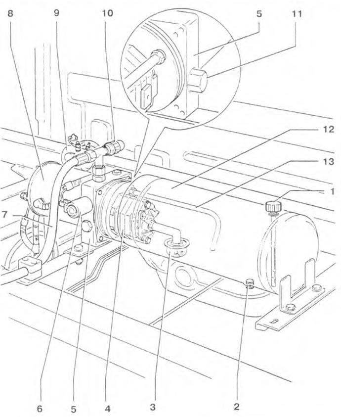
Figure 10.21. Electrohydraulic unit: 1 - Lid; 2 - Drain plug; 3 - Oil filter; 4 - Hydraulic pump; 5 - Control unit; 6 - Lift valve (opens when the body is lowered); 7 - Oil pressure line; 8 - Hydraulic pump electric motor; 9 - Hydraulic pump motor switch relay; 10 - Pressure switch; 11 - Overpressure valve (in the control unit under the cover); 12 - Tank (volume 6 l); 13 - Oil drain line.
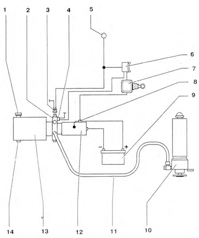
Figure 10.22. Hydraulic diagram of the lift: 1 - Lid; 2 - Control unit; 3 - Pressure switch; 4 - Lift valve (opens when the body is lowered); 5 - Terminal 15+; 6 - Button with signal light; 7 - Limit switch (switches off the engine of the electro-hydraulic unit via a stop cable when the maximum angle of the body is reached); 8 - Hydraulic pump electric motor switch relay; 9 - Battery; 10 Multi-piston hydraulic cylinder; 11 - Oil pressure line; 12 - Hydraulic pump; 13 - Cistern (the hydraulic pump is located in the tank); 14 - Drain plug.
The marking and length of the locking cable depending on the vehicle model are given in Table 10.1.
Table 10.1. Marking and length of the locking cable depending on the vehicle model
| Car model | Wheelbase | Marking | Cable length, mm |
| LT 35 | 3000 | 9053 182 | 400 |
| LT 35 | 3550 | 9053 184 | 515 |
| LT 35 double cab | 4025 | 9053 183 | 445 |
| LT 46 | 3550 | 9053 184 | 515 |
| LT 46 with double cab | 3550 | 9053 183 | 445 |
| LT 46 with double cab | 4025 | 9053 184 | 515 |
(The original text is available on the portal: www.VWManual.ru)
Visitor comments