
English Русский
Български
Беларускі
Український
Српски
Hrvatski
Română
Polski
Slovenský
Magyar
  |  Articles  |  Sitemap  |  Contacts  |    |
Car maintenance Ford Car maintenance Hyundai Car maintenance Chevrolet Car maintenance BMW Car maintenance Audi Car maintenance Opel Car maintenance AvtoVAZ
VWmanual.ru


Main   Passat   Golf   Polo   Touareg   Tiguan   Sharan   Transporter   Others  
LT 28 (1975-1991) LT 2D (1996-2003) Beetle (1960-1986) Caddy 3 (2003-2010)

Dashboard (VW Lt 2d)

  • Main
  • Volkswagen
  • LT 2D
  • Body
  • Body elements
  • Dashboard
            0


Contents: Removal ↓ Installation ↓

Removal


1. Disconnect the negative cable from the battery.

2. Remove the radio.

3. Turn screw 1 by 90° and remove cover 2 from the relay box (arrow) (Fig. 10.23)
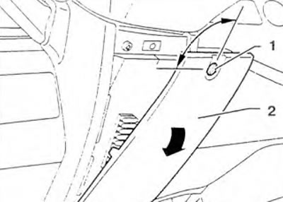
Figure 10.23. Turn screw 1 90° and remove cover 2 from the relay box (arrow).

Figure 10.23. Turn screw 1 90° and remove cover 2 from the relay box (arrow).


4. Unscrew screws 2 and unscrew nut 3 (figure 10.24). Remove the lower panel 1 from the steering column.
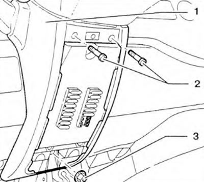
Figure 10.24. Unscrew screws 2 and unscrew nut 3. Remove lower panel 1 from the steering column.

Figure 10.24. Unscrew screws 2 and unscrew nut 3. Remove lower panel 1 from the steering column.


5. Unscrew screw 1 and tighten nut 4 with washer 3 (figure 10.25). Remove relay box 2 and disconnect the wiring connector from the ignition switch.
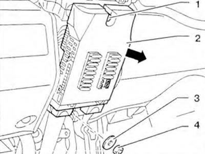
Figure 10.25. Unscrew screw 1 and tighten nut 4 with washer 3. Remove relay block 2 and disconnect…

Figure 10.25. Unscrew screw 1 and tighten nut 4 with washer 3. Remove relay block 2 and disconnect the wiring connector from the ignition switch.


6. Remove the steering wheel.

7. Disconnect the wiring connectors (arrows) (figure 10.26).
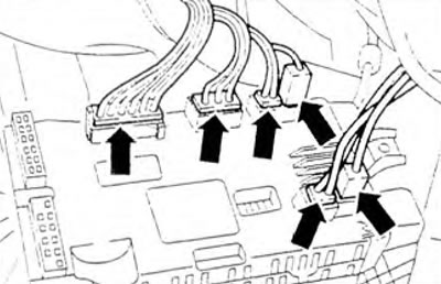
Figure 10.26. Disconnect the wiring connectors (arrows).

Figure 10.26. Disconnect the wiring connectors (arrows).


8. Remove the screws (arrows) (figure 10.27). Remove the top panel from the ignition switch on the steering column 1.
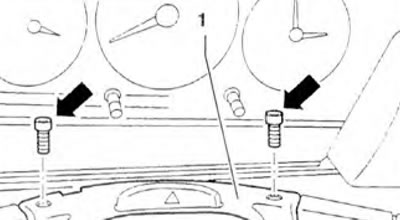
Figure 10.27. Remove the screws (arrows). Remove the top panel from the ignition switch on the…

Figure 10.27. Remove the screws (arrows). Remove the top panel from the ignition switch on the steering column 1.


9. Remove decorative panel 4 from the headlight range adjuster, disconnect wiring connector 1. Mark vacuum pipes 1 and 2 and disconnect them (figure 10.28).
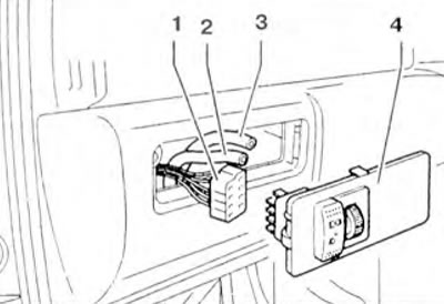
Figure 10.28. Remove decorative panel 4 from the headlight range adjuster, disconnect wiring…

Figure 10.28. Remove decorative panel 4 from the headlight range adjuster, disconnect wiring connector 1. Mark vacuum pipes 1 and 2 and disconnect them.


10. Unscrew the screws (arrows) and remove panel 1 (figure 10.29).
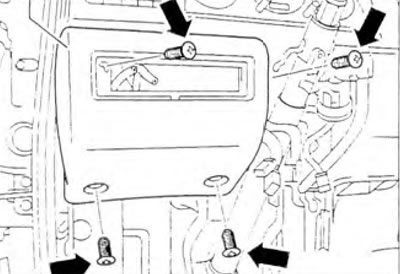
Figure 10.29. Unscrew the screws (arrows) and remove panel 1.

Figure 10.29. Unscrew the screws (arrows) and remove panel 1.


11. Remove the speaker cover 1 and unscrew the screw (arrow) (figure 10.30).
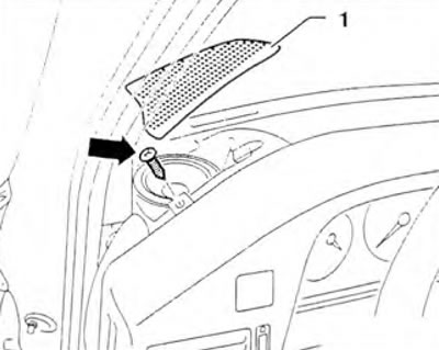
Figure 10.30. Remove speaker cover 1 and unscrew the screw (arrow).

Figure 10.30. Remove speaker cover 1 and unscrew the screw (arrow).


12. Remove cover 1 of the switches and unscrew the screw (arrow) (figure 10.31).
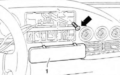
Figure 10.31. Remove cover 1 of the switches and unscrew the screw (arrow).

Figure 10.31. Remove cover 1 of the switches and unscrew the screw (arrow).


13. Remove the rotary knobs of the heating system controls 2 and unscrew the nuts 1 (figure 10.32).
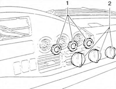
Figure 10.32. Remove the rotary knobs of the heating system controls 2 and unscrew the nuts 1.

Figure 10.32. Remove the rotary knobs of the heating system controls 2 and unscrew the nuts 1.


14. Open the glove box and remove the screws (arrow) (figure 10.33).
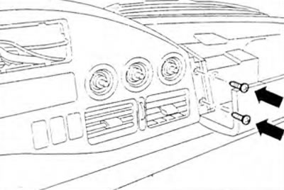
Figure 10.33. Open the glove compartment and remove the screws (arrow).

Figure 10.33. Open the glove compartment and remove the screws (arrow).


15. Lift up the decorative panel 1 of the instrument panel, disconnect the wiring connectors and remove the panel 1 by moving it forward (figure 10.34).
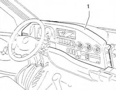
Figure 10.34. Lift up decorative panel 1 of the instrument panel, disconnect the wiring connectors…

Figure 10.34. Lift up decorative panel 1 of the instrument panel, disconnect the wiring connectors and remove panel 1, moving it forward.


16. Remove the screws (arrow) and move the instrument cluster 1 back (figure 10.35).
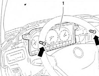
Figure 10.35. Remove the screws (arrow) and move the instrument cluster 1 back.

Figure 10.35. Remove the screws (arrow) and move the instrument cluster 1 back.


17. Disconnect connectors 1 and 2 by pressing on the fastening tabs (arrow A) and move the retainer 3 upwards (arrow B) (figure 10.36).
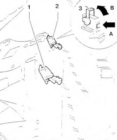
Figure 10.36. Disconnect connectors 1 and 2 by pressing on the fastening ears (arrow A) and move…

Figure 10.36. Disconnect connectors 1 and 2 by pressing on the fastening ears (arrow A) and move the retainer 3 upwards (arrow B).


18. Remove the instrument cluster from the instrument panel.

19. Remove the left speaker 1 and unscrew the screw 2 (figure 10.37).
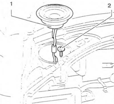
Figure 10.37. Remove the left speaker 1 and unscrew the screw 2.

Figure 10.37. Remove the left speaker 1 and unscrew the screw 2.


20. Remove cover 2 of the right speaker and take out speaker 1. Remove the screw (arrow) (figure 10.38).
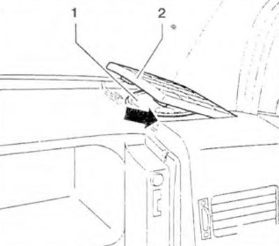
Figure 10.38. Remove cover 2 of the right speaker and take out speaker 1. Unscrew the screw (arrow).

Figure 10.38. Remove cover 2 of the right speaker and take out speaker 1. Unscrew the screw (arrow).


21. Open the cover 1 of the glove box and unscrew the screws 2 (figure 10.39). Remove glove compartment cover 1 from the instrument panel so that limiter 3 is released.
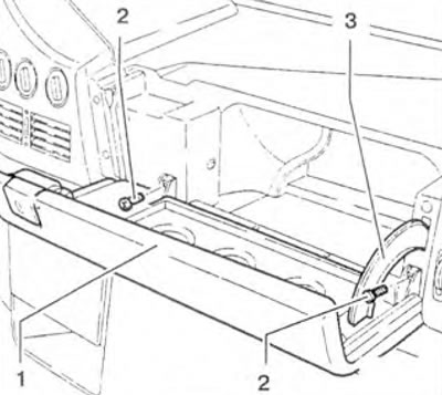
Figure 10.39. Open glove box cover 1 and unscrew screws 2. Remove glove box cover 1 from the…

Figure 10.39. Open glove box cover 1 and unscrew screws 2. Remove glove box cover 1 from the instrument panel so that limiter 3 is released.


22. Remove screws 1 (figure 10.40).
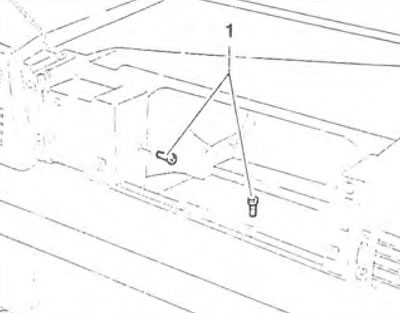
Figure 10.40. Remove screws 1.

Figure 10.40. Remove screws 1.


23. Remove cover 1 of the instrument panel (figure 10.41).
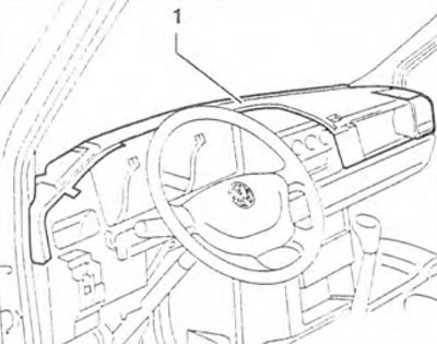
Figure 10.41. Remove instrument panel cover 1.

Figure 10.41. Remove instrument panel cover 1.


24. Turn screw 1 and remove cover 2 from the floor on the passenger side (figure 10.42).
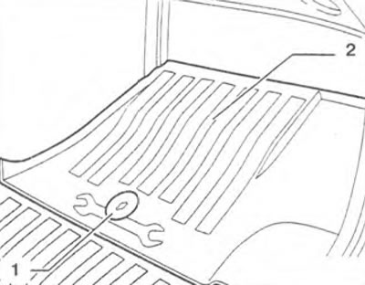
Figure 10.42. Turn screw 1 and remove cover 2 from the floor on the passenger side.

Figure 10.42. Turn screw 1 and remove cover 2 from the floor on the passenger side.


25. Remove screw 1 from center console 2 (figure 10.43).
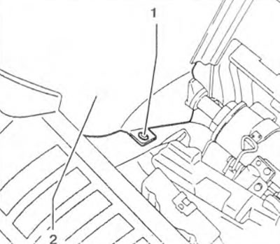
Figure 10.43. Remove screw 1 from center console 2.

Figure 10.43. Remove screw 1 from center console 2.


26. Lift up the floor covering 1 on the driver's side and remove screw 2 (figure 10.44).
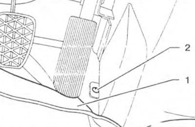
Figure 10.44. Lift floor covering 1 on the driver's side and remove screw 2.

Figure 10.44. Lift floor covering 1 on the driver's side and remove screw 2.


27. Remove the screws (arrows) under the ashtray 1 (figure 10.45).
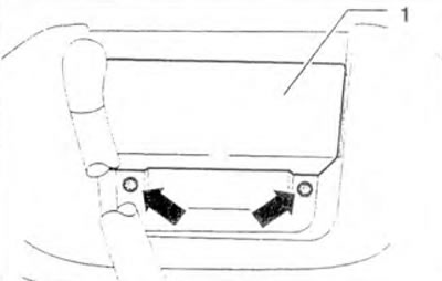
Figure 10.45. Remove the screws (arrows) under the ashtray 1.

Figure 10.45. Remove the screws (arrows) under the ashtray 1.


28. Remove the central instrument panel console, disconnect the wiring connectors from the cigarette lighter.

29. Unscrew the screws (arrows) and remove the decorative panel 1 from the instrument panel (figure 10.46).
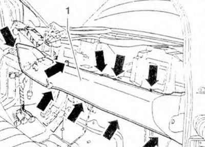
Figure 10.46. Unscrew the screws (arrows) and remove the decorative panel 1 from the instrument…

Figure 10.46. Unscrew the screws (arrows) and remove the decorative panel 1 from the instrument panel.


30. Cut the wiring tie straps 1 along the instrument panel 2 (figure 10.47).
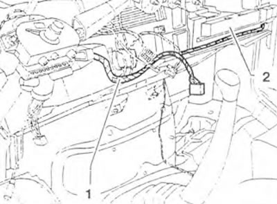
Figure 10.47. Cut the wiring tie straps 1 along the instrument panel 2.

Figure 10.47. Cut the wiring tie straps 1 along the instrument panel 2.


31. Remove the heater.

32. Unscrew bolts 4 (along the windshield) and 2 (in the engine compartment), side bolts 3 and remove the instrument panel 1 from the vehicle (figure 10.48).

Installation


33. Installation is carried out in the reverse order of removal.
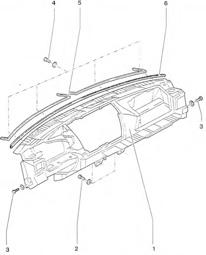
Figure 10.48. Unscrew bolts 4 (along the windshield) and 2 (in the engine compartment), side bolts…

Figure 10.48. Unscrew bolts 4 (along the windshield) and 2 (in the engine compartment), side bolts 3 and remove the instrument panel 1 from the vehicle.

This article is available at russian, bulgarian, belarusian, ukrainian, serbian, croatian, romanian, polish, slovak, hungarian
The text has been checked: Kolesnikov Artem

Share information:

Previous articles
Three-way tipper body
Rear doors
Sliding door
Front door
Front bumper
Old version hood
Next articles


Similar articles from other manuals for VW cars:
Dashboard switches Passat B3 (1988-1993)
Dashboard Golf 1 (1974-1984, petrol)
Car dashboard Polo 4 (2001-2009)
Instrument visor (dashboard) on the instrument panel Transporter T4 (1990-2003)
Link to this page in different formats


Visitor comments


No comments yet


How much will 10 + 47 =


Caddy 3 
  • General information
  • User manual
  • Daily care
  • Maintenance
  • Petrol engines 1.4 l
  • Engine repair
  • Cooling and lubrication system
  • Power and exhaust system
  • Petrol engines 1.6 l
  • Engine repair
  • Cooling and lubrication system
  • Power and exhaust system
  • Diesel engines
  • Engine repair
  • Cooling and lubrication system
  • Power and exhaust system
  • Transmission
  • Mechanical gearbox 0AH
  • Mechanical gearbox 0A4
  • Drive shafts
  • Chassis
  • Car suspension
  • Steering
  • Brake system
  • Body and wiring diagrams
  • Interior and exterior
  • Electrical circuits
Beetle 
  • General information
  • Maintenance
  • Power unit
  • Engine repair
  • Cooling and lubrication system
  • Supply system
  • Exhaust system
  • Transmission
  • Clutch
  • Car gearbox
  • Chassis
  • Front suspension
  • Rear suspension
  • Steering
  • Brake system
  • Wheels and tires
  • Body
  • Exterior
  • Electrical equipment
  • Equipment and devices
  • Power devices
  • Electrical circuits
LT 2D 
  • General information
  • User manual
  • Maintenance
  • Power unit
  • Petrol engines 2.3 l
  • Diesel engines 2.5 l
  • Diesel engines 2.8 l
  • Injection system (diesel 2.8 l)
  • Transmission
  • Clutch
  • Manual gearbox
  • Differential
  • Chassis
  • Car suspension
  • Steering system
  • Brake system
  • Body
  • Body elements
  • Heating system
  • Electrical equipment
  • Equipment and devices
  • Electrical circuits
LT 28 
  • General information
  • Maintenance
  • Power unit
  • Petrol engines 2.0L
  • Petrol engines 2.4L
  • Diesel engines
  • Cooling and heating
  • Fuel and exhaust system
  • Ignition system
  • Transmission
  • Clutch
  • Car gearbox
  • Cardan shaft
  • Rear axle
  • Chassis
  • Brake system
  • Car suspension
  • Steering system
  • Body
  • Body elements
  • Doors, locks and windows
  • Electrical equipment
  • Power devices
  • Equipment and devices
  • Electrical circuits
VWmanual.ru © 2016-2026 | Mobile version | News and articles | Sitemap: EN BG BY UA RS HR RO PL SK HU | Write message | Site search
Passat B2 • Passat B3 • Passat B4 • Passat B5 • Passat B6 • Golf 1, diesel • Golf 1, petrol • Golf 2, petrol • Golf 2 • Golf 3 • Golf 4 • Golf 5 • Polo 3 • Polo 4 • Touareg 1 • Tiguan 1 • Sharan 1 • Transporter T3 • Transporter T4 • LT 28 • LT 2D • Beetle • Caddy 3 •
Our website uses cookies to ensure functionality and convenience.