



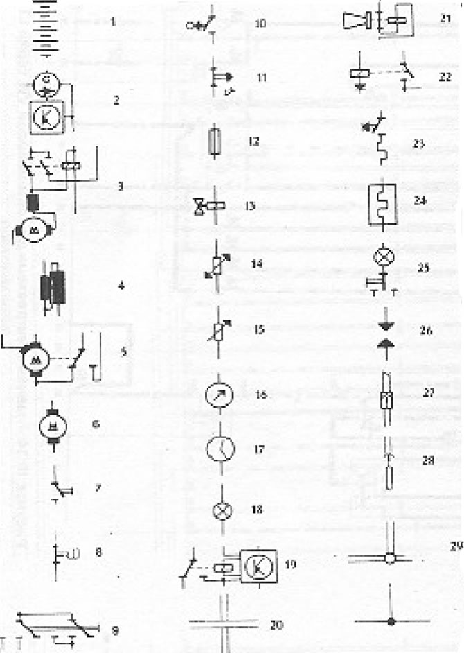
Figure 10.32. Symbols used in electrical circuits: 1 - Battery; 2 - Generator with voltage regulator; 3 - Starter; 4 - Ignition coil; 5 - Windscreen wiper motor - 2 speeds; 6 - Electric motor; 7 - Switch (manual on/off control); 8 - Switch (pressure-actuated); 9 - Switch (mechanically driven); 10 - Switch (mechanically driven); 11 - Switch (thermo); 12 - Fuse; 13 - Solenoid valve; 14 - Sensor for coolant temperature sensor; 15 - Sensor for fuel level sensor; 16 - Device; 17 - Hours; 18 - Light bulb; 19 - Relay (electronic control); 20 - Crossing wires (no connection); 21 - Sound signal; 22 - Relay (with diode); 23 - Cigarette lighter; 24 - Rear window defroster; 25 - Interior lighting; 26 - Ignition spark; 27 - Flat connector; 28 - Connector (multi-plug); 29 - Wire connection, can be disconnected; 30 - Connecting wires (fixed).
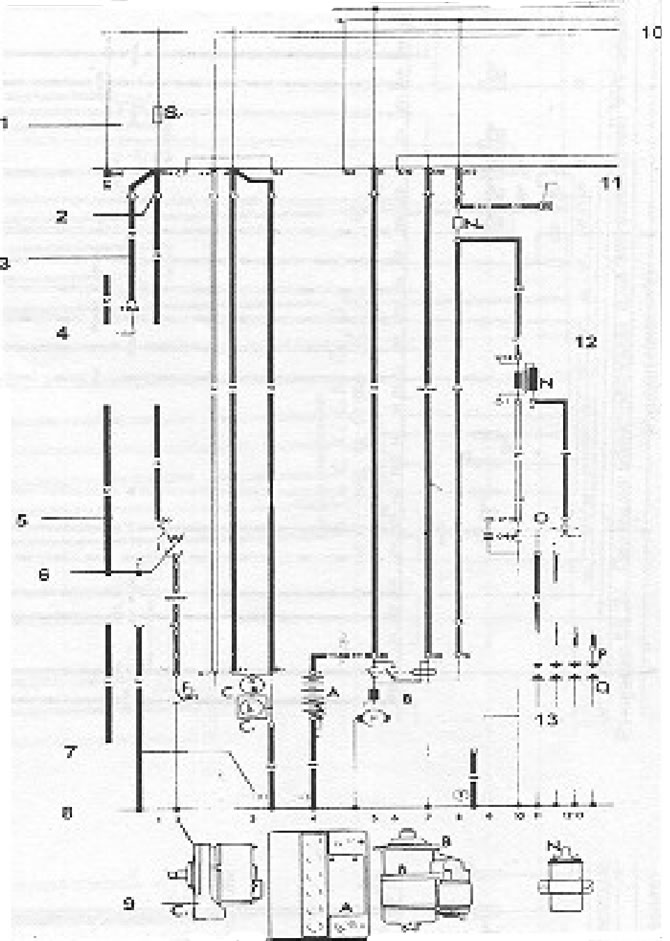
Figure 10.33. Sample electrical circuit diagram with explanations: 1 - The grey area is the relay board with the fuse holder; 2 - Wire cross-section in mm sq; 3 - Wire colors (the actual colors as mounted on the vehicle are shown); 4 - Numbers/combinations of numbers - these indicate individual contacts in multi-plugs, for example T 10/4 means: T10 = ten-pin connector, 4/ = contact 4; 5 - Symbols (in a summer cottage - a light bulb); 6 - Designations of parts. Using the notation system, you can find the part of the circuit where the current flows; for example W = interior lighting; 7 - The numbers in circles indicate the location of the grounding points (see notation); 8 - Wire numbers - help locate specific parts of the circuit (see notation); 9 - Illustrations of parts and components whose symbols are indicated above; 10 - All switches and contacts are shown in the "off" position. The various contacts in the switch are shown in the circuit to which they functionally belong; 11 - Numbers in yellow squares indicate that the wire ends in this circuit and you need to look for it in other parts of the circuit; 12 - Contacts with numbers found on actual parts; 13 - Internal connections (thin lines). These connections cannot be detected as wires. However, they will transmit current one way or another. Therefore, they make it possible to check the presence of current inside a component or device.
[The information is posted on this website: www.VWMANUAL.ru]
Visitor comments