




2. Press "08" to select the "Read measured value block" function and confirm by pressing the "Q" button. The display should show the following information:

3. Press "007" to select the "Display Group 7" function and press "Q". The display should show the following information:

4. If there is no actual display in field 3 or the temperature displayed is 136.8°C, check the temperature sensor and wires.
5. Click "→".
6. Press "06" to select the "Complete Output" function and confirm by pressing the "Q" button.
7. Turn off the ignition.
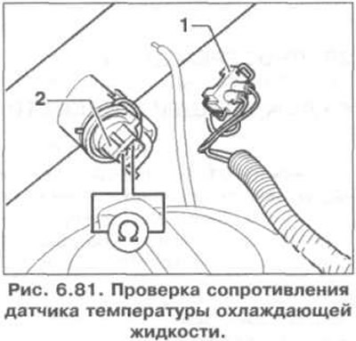
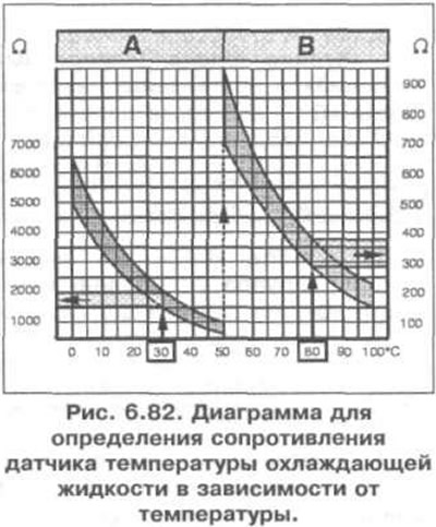
8. Disconnect the connector of wiring 1 of the sensor 2 (Fig. 6.81). Measure the resistance between the sensor contacts. The specified value is shown in Fig. 6.82. Area A shows the resistance in the temperature range of 0-50°C, area B - the resistance in the temperature range of 50-100°C. For example, a temperature of 30°C corresponds to a resistance of 1500-2000 Ohm; temperature 80°C corresponds to resistance 275-375 Ohm.
9. If the specified value is not achieved, replace the sensor.
10. If the specified value is reached, connect the VAG 1598/18 tester to the engine control unit wiring harness (fig. 6.55).
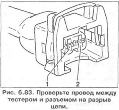
11. Check the wire between the tester and the connector for open circuit: contact 1 + socket 64, contact 2 + socket 33 (Fig. 6.83). Specified value: 1.5 Ohm.
12. Additionally, check the wires for short circuits to each other, to the vehicle ground, and to the positive battery terminal. Specification resistance: ∞ Ohm.
13. If no fault is found in the wires, then replace the engine control unit.
Visitor comments