




2. Press "08" to select the "Read measured value block" function and confirm by pressing the "Q" button. The display should show the following information:

3. Press "007" to select the "Display Group 007" function and press "Q". The display should show the following information:

4. If field 1 does not display real information or it is replaced with a temperature of -5.4°C or -5.6°C, check the sensor and the wires going to it.
5. Click "→".
6. Press "06" to select the "Complete Output" function and confirm by pressing the "Q" button.
7. Turn off the ignition.
On vehicles with a 68-pin control unit wiring connector
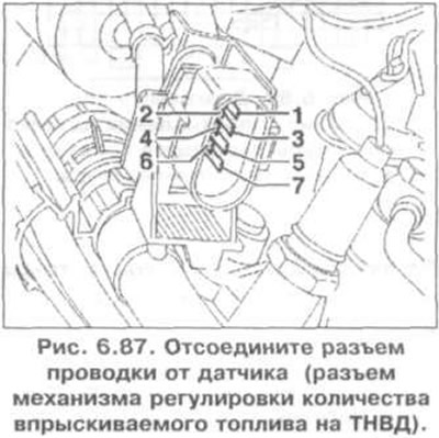
8. Disconnect the wiring connector from the sensor (connector of the fuel injection quantity adjustment mechanism on the high pressure fuel pump) (Fig. 6.87).
On vehicles with 80-pin control unit wiring connector
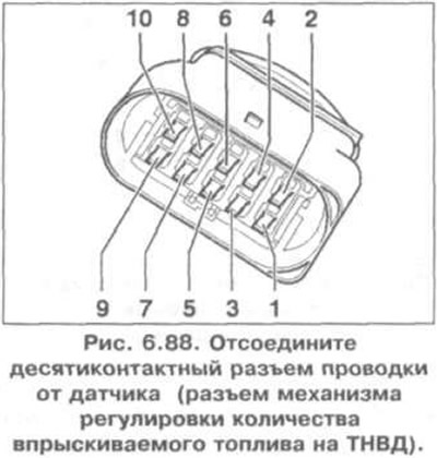
9. Disconnect the ten-pin wiring connector from the sensor (connector of the fuel injection quantity adjustment mechanism on the high pressure fuel pump) (Fig. 6.88).
For all cars
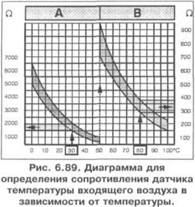
10. Measure the resistance between contacts 4 and 7. The specified value is shown in Fig. 6.89. Area A shows the resistance in the temperature range of 0-50°C, area B shows the resistance in the temperature range of 50-100°C. For example, a temperature of 30°C corresponds to a resistance of 1500-2000 Ohm; temperature 80°C corresponds to resistance 275-375 Ohm.
11. If the specified value is not achieved, replace the fuel injection pump.
12. If the specified value is reached:
On vehicles with a 68-pin control unit wiring connector
- Connect the VAG 1598/18 tester to the engine control unit wiring harness (fig. 6.54);
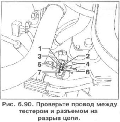
- Check the wire between the tester and the connector for open circuit: contact 4 + socket 63, contact 7 + socket 33 (Fig. 6.90). Specified value: 1.5 Ohm;
- Additionally, check the wires for short circuits to each other, to the vehicle ground, and to the positive battery terminal. Specification resistance: ∞ Ohm;
On vehicles with 80-pin control unit wiring connector
- Connect the VAG 1598/22 tester to the engine control unit wiring harness (fig. 6.56);
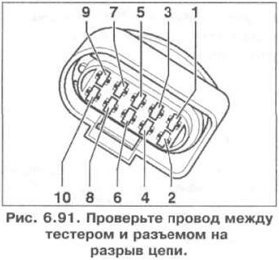
- Check the wire between the tester and the connector for open circuit: contact 4 and socket 76, contact 7 and socket 53 (Fig. 6.91). Specified value: 1.5 Ohm;
- Additionally, check the wires for short circuits to each other, to the vehicle ground, and to the positive battery terminal. Specification resistance: ∞ Ohms.
For all cars
13. If no fault is found in the wires, replace the engine control unit.
Visitor comments