
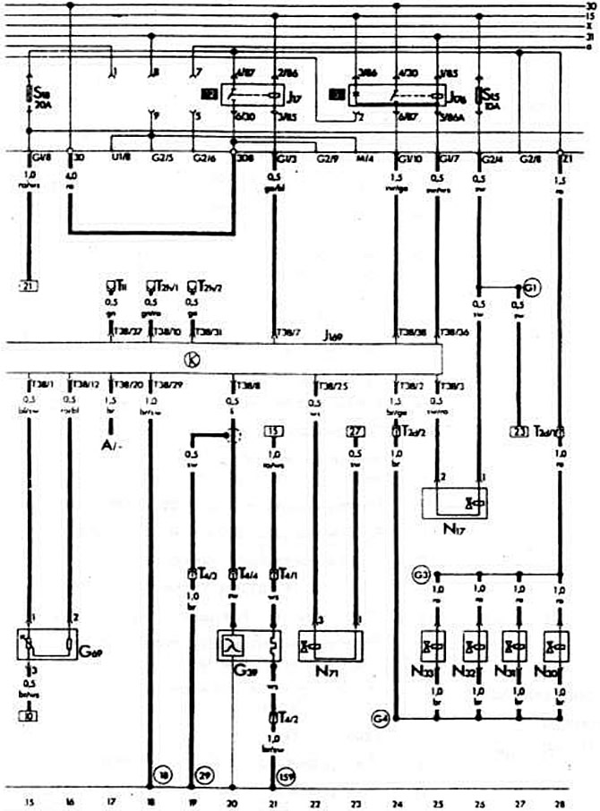
The area at the top of the diagram can be shaded in gray and indicates the internal circuit of the mounting block with relays and fuses. Lines within the zone marked 30.15.X, etc., represent the ignition switch or instrument and starter switch terminals. Numbers on a black background next to the relay ([12], [3]) indicate the location of the relay in the mounting block.
Notation S15, S18 indicate the serial number of the fuse in the mounting block.
By notation J17, N17, G6g define the name of the element given in the list of circuit elements. The numbers next to the element 4/87. 2/86 and others indicate the pin numbers of the mounting block connector (4 and 2) and element (87 and 86). The connectors of the mounting block are designated by letters and numbers, for example G2 / 6 - pin 6 of the G2 connector. On other elements, the connectors may be designated in the same way (For example. T38/37) Or just numbers.
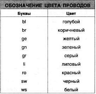
In the wire breaks, the numbers indicate the cross-sections of the wires in mm2, and in letters - their colors, deciphered below. Numerical designations at the ends of the wires ([21], [15]) indicate the path along which the wire is laid.
The designation of the connectors on the wires is deciphered as follows: T4/3 - 3rd pin of the 4-pin T connector. Connection points with «weight» indicated by numbers in circles: (18), (29).
Visitor comments