



Typical schematic diagram - 6-cylinder models produced in 1986 and 1987
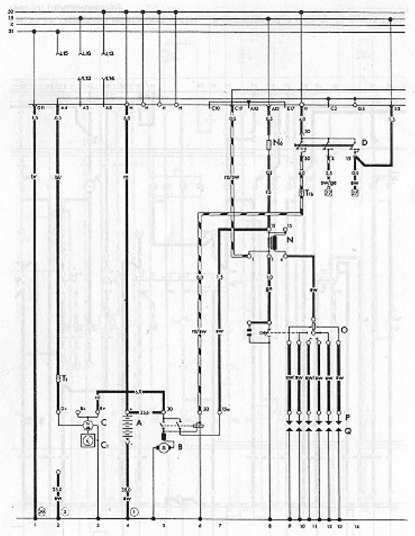
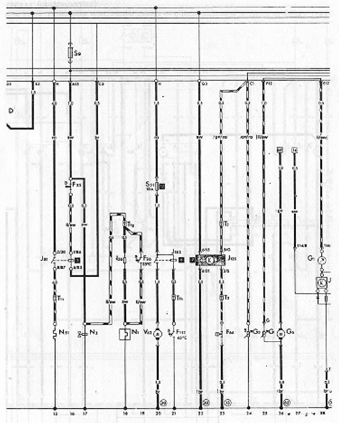
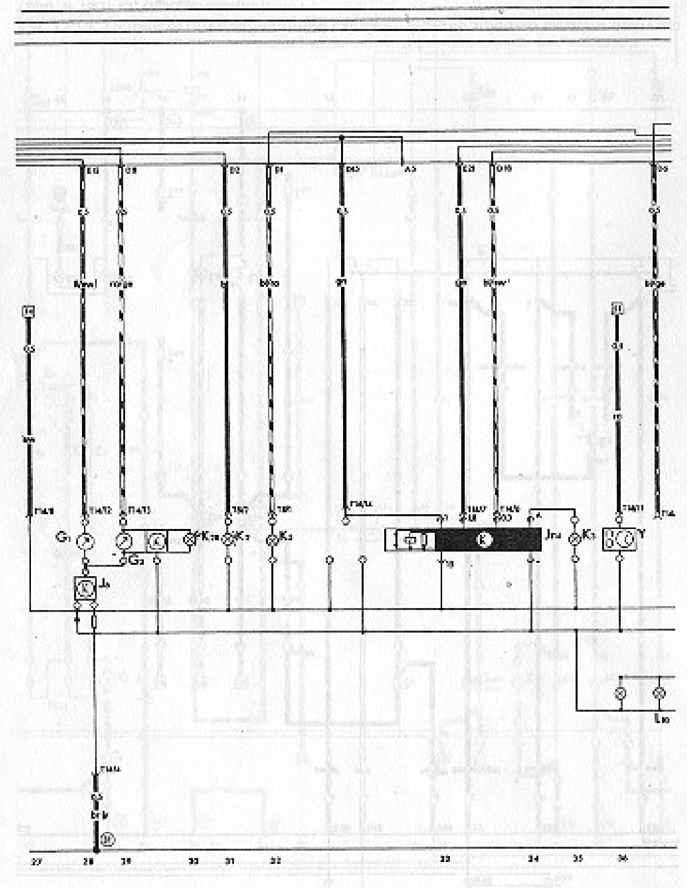
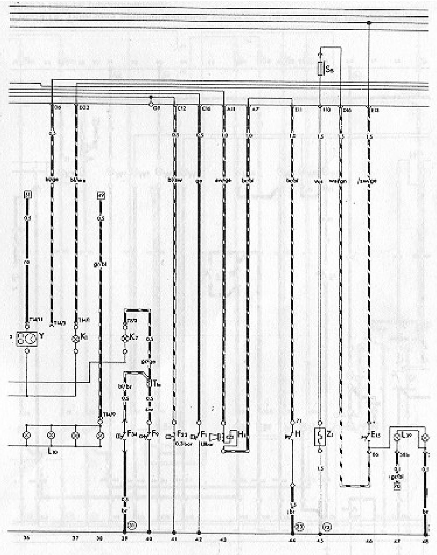
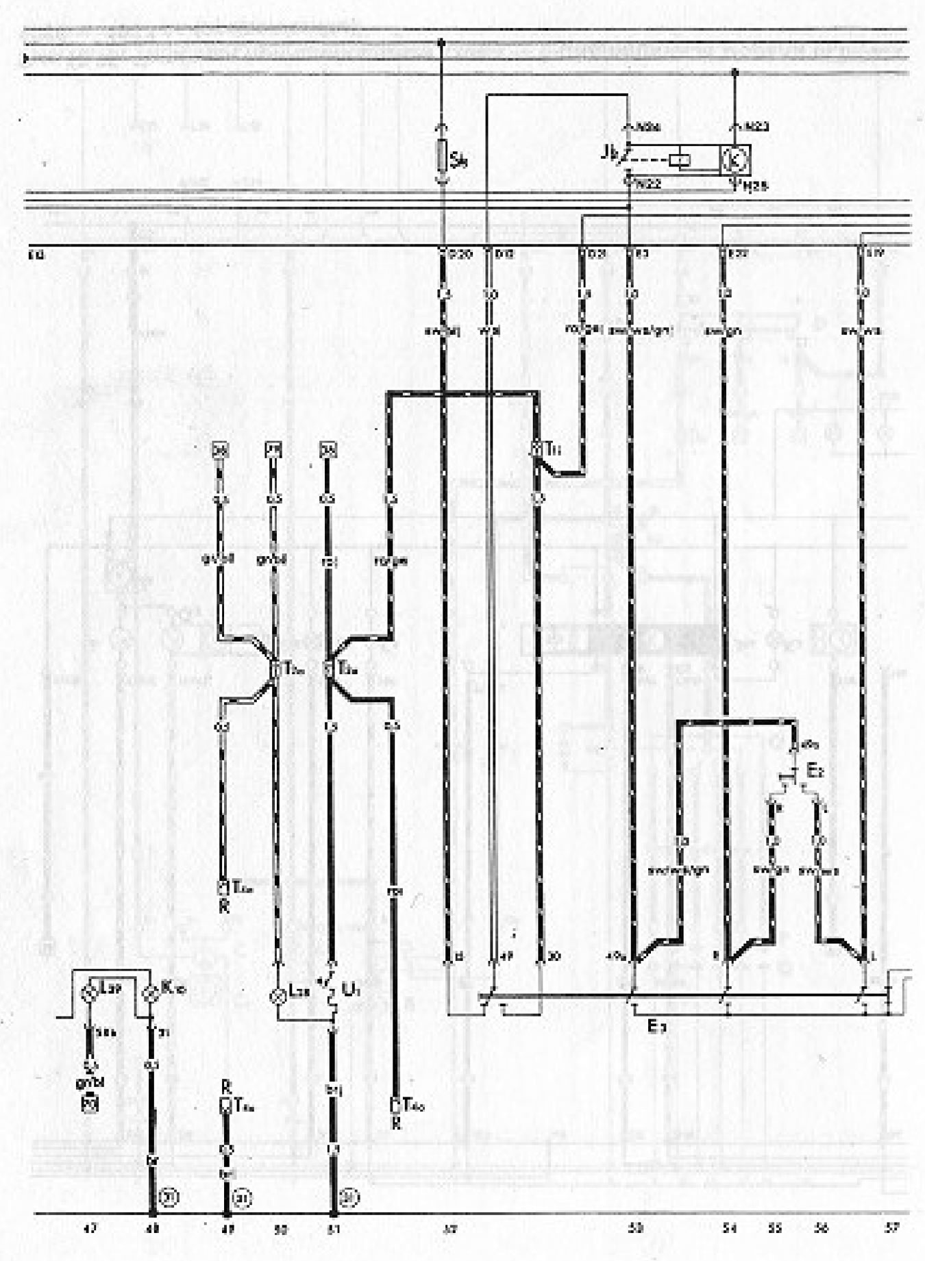
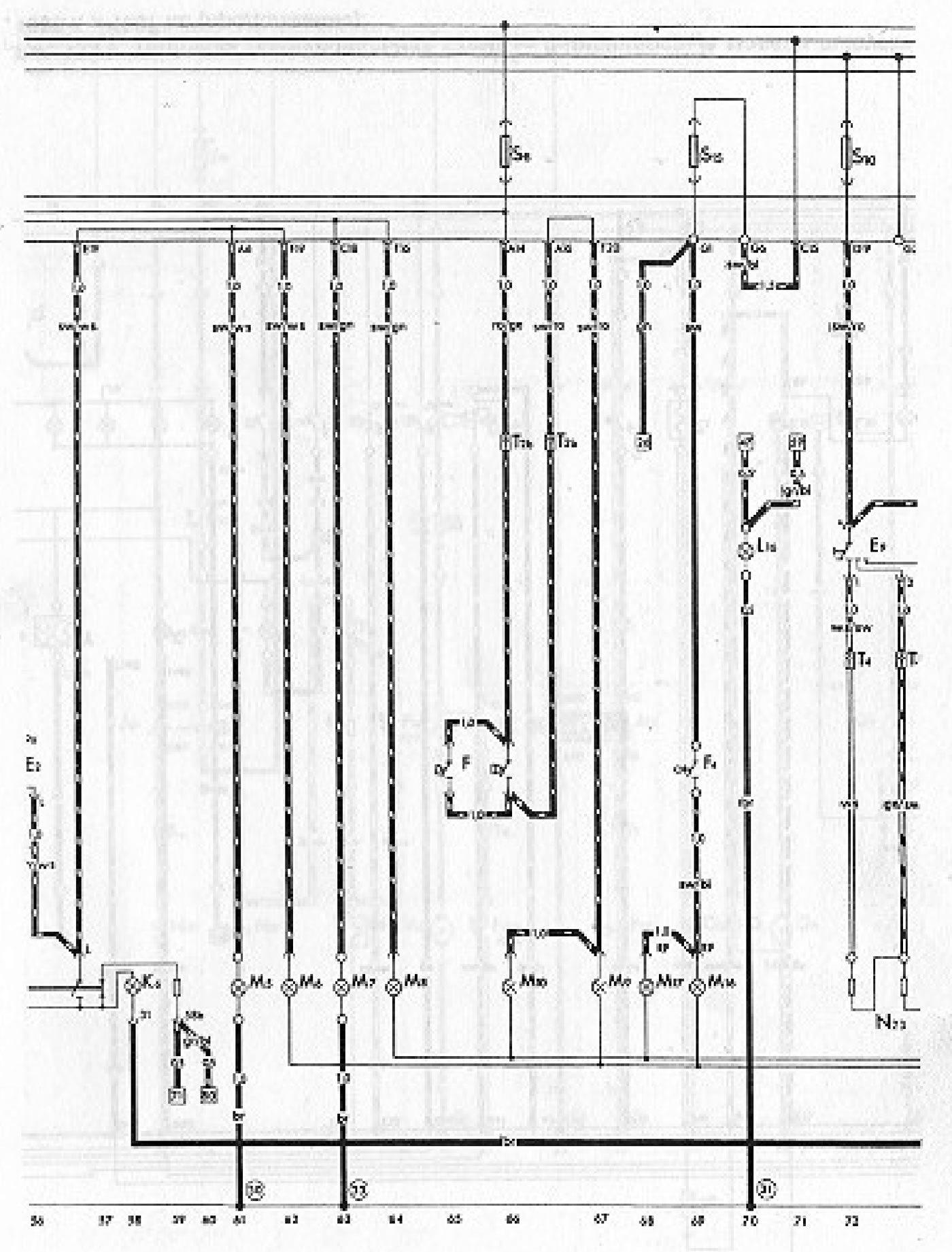
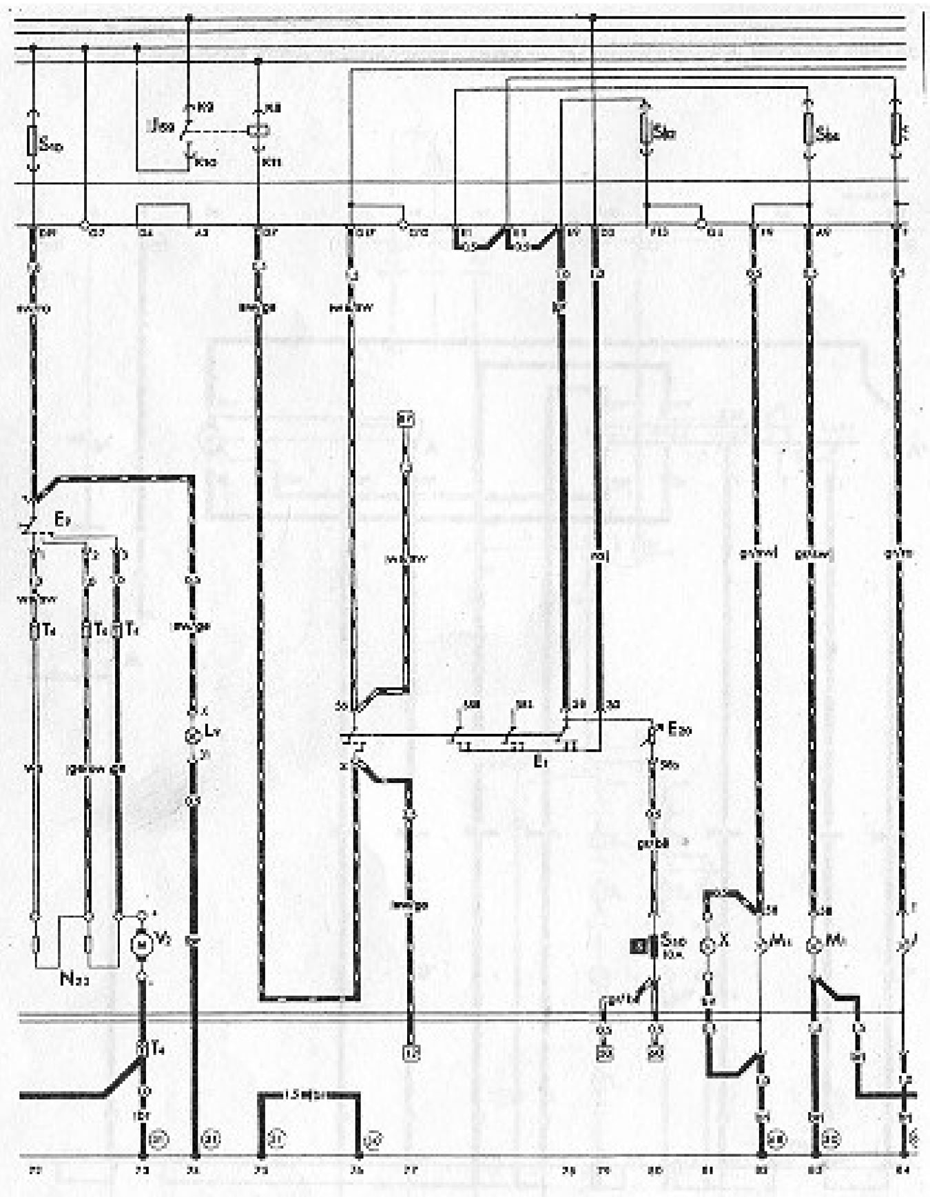
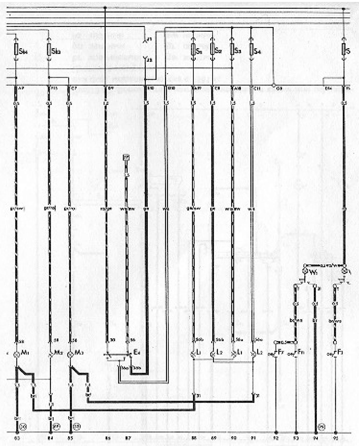
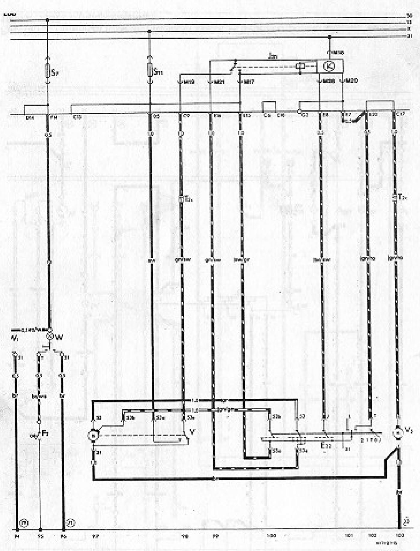
Conventional symbols for the diagram
| Designation | Device | Track number |
| A | Battery | 4 |
| IN | Starter | 5-7 |
| WITH | Generator | 2,3 |
| C1 | Voltage regulator | 2,3 |
| D | Ignition/starter switch | 10-14 |
| E1 | Light switch | 76-80 |
| E2 | Turn signal switch | 55,56 |
| E3 | Hazard warning switch | 52-59 |
| E4 | Headlight dimmer switch | 86,87 |
| E9 | Fresh air blower switch | 72,73 |
| E15 | Rear window defroster switch | 46-48 |
| E20 | Instrument/dashboard dimmer | 80 |
| E22 | Windshield wiper switch (pause mode) | 100-102 |
| F | brake light switch | 65,66 |
| F1 | Oil pressure switch (1.8 bar) | 42 |
| F2 | Contact switch on the door (front left) | 95 |
| F4 | reverse light switch | 69 |
| F7 | Contact switch on the door (rear sliding door) | 92 |
| F9 | Handbrake on indicator light switch | 40 |
| F11 | Contact switch on the rear door | 93 |
| F22 | Oil pressure switch (0.3 bar) | 41 |
| F26 | Automatic choke thermal switch, front air intake pipe | 19 |
| F34 | Low brake fluid level alarm contact | 39 |
| F35 | Intake manifold heater thermal switch | 16 |
| F66 | Low coolant level warning light switch | 23 |
| F112 | Carburetor cooling air blower thermal switch | 21 |
| G | Fuel level sensor | 25 |
| G1 | Fuel level indicator | 28 |
| G2 | Coolant temperature sensor | 24 |
| GЗ | Coolant temperature gauge | 29 |
| G6 | Electric fuel pump | 26 |
| N | Horn switch | 44 |
| H1 | Sound signal | 43 |
| J2 | Alarm relay | 53,54 |
| J6 | Voltage stabilizer | 28 |
| J31 | Windscreen washer/wiper time delay relay | 98-101 |
| J59 | Reset relay (for contact X) | 74,75 |
| J81 | Intake manifold heater relay, on auxiliary relay adapter | 15,16 |
| J114 | Oil pressure monitoring system control unit | 33,34 |
| J120 | Low brake fluid level warning light switch, on auxiliary relay adapter | 22,23 |
| J183 | Carburetor cooling air blower relay (time relay) | 20,21 |
| K1 | High beam indicator light | 37 |
| K2 | Generator warning light | 31 |
| KZ | Low oil pressure warning light | 35 |
| K5 | Direction indicator light | 32 |
| K6 | Hazard warning light | 58 |
| K7 | Dual brake circuit and handbrake warning light | 39 |
| K10 | Rear window defroster warning light | 48 |
| K28 | High Temperature/Low Coolant Level Warning Light | 30 |
| L1 | Dual-filament headlight bulb, left | 88,90 |
| L2 | Double filament headlight bulb, right | 89,91 |
| L9 | Light switch illumination lamp | 74 |
| L10 | Instrument panel insert lighting lamp | 36-38 |
| L16 | Fresh air ventilation control illumination lamp | 70 |
| L28 | Cigarette lighter illumination lamp | 50 |
| L39 | Rear window defroster switch illumination lamp | 47 |
| M1 | Left side marker light | 83 |
| M2 | Tail light, right | 84 |
| M3 | Side light, right | 85 |
| M4 | Tail light, left | 82 |
| M5 | Direction indicator, front left | 61 |
| M6 | Direction indicator, rear left | 62 |
| M7 | Direction indicator, front right | 63 |
| M8 | Direction indicator, rear right | 64 |
| M9 | Brake light, left | 67 |
| M10 | Brake light, right | 66 |
| M16 | Reverse light, left | 69 |
| M17 | Reverse light, right | 68 |
| N | Ignition coil | 8 |
| N1 | Automatic choke | 18 |
| N3 | Air bypass shut-off valve | 17 |
| N6 | Series resistance | 8 |
| N23 | Series resistance of fresh air blower | 72 |
| N36 | Series resistance of automatic choke | 18 |
| N51 | Intake manifold heater heating element | 15 |
| ABOUT | Distributor | 9-13 |
| R | Spark plug terminal | 9-13 |
| Q | Spark plugs | 9-13 |
| R | Radio receiver connector | 49,51 |
| S1-S15 | Fuses in the fuse box | |
| S50 | 10A fuse, terminal 58b, on the auxiliary relay adapter | 80 |
| S51 | Carburetor cooling air blower fuse | 20 |
| T1 | Single-pole connector in the engine compartment | |
| T1a | Single-pole connector, behind the dashboard | |
| T1b | Single-pole connector, behind the relay panel | |
| T1s | Single-pole connector, behind the dashboard | |
| T1d | Single-pole connector, near the carburetor | |
| T1h | Single-pole connector, near the carburetor | |
| T1i | Single-pole connector, behind the dashboard | |
| T2 | 2-pole connector, behind the relay panel | |
| T2a | 2-pin connector, behind the dashboard | |
| T2b | 2-pin connector, behind the dashboard | |
| T2s | 2-pin connector, behind the dashboard | |
| T4 | 4-pin connector behind the dashboard | |
| T4a | 4-pin connector behind the dashboard | |
| T8/ | 8-pin connector, on the dashboard insert | |
| T14/ | 14-pin connector on the instrument panel insert* | |
| U1 | Cigarette lighter | 51 |
| V | Windshield wiper motor | 97,98 |
| V2 | Fresh air blower | 73 |
| V5 | Windshield washer pump | 103 |
| V62 | Carburetor cooling blower, on the left side of the engine | 20 |
| W | Interior light, front | 95,96 |
| W1 | Interior light, rear/trunk | 93,94 |
| X | License plate light | 82 |
| Y | Watch | 36 |
| Z1 | Rear window defroster | 45 |
[The information is presented on the website vwmanual.ru]
*The T14 connector contacts are designated according to the PCB layout of the instrument cluster insert, not according to the wiring harness connected to the connector.
| 1 | Ground wire from the battery to the body |
| 3 | Ground wire from the engine to the body |
| 15 | Grounding point on the cylinder head |
| 23 | Ground wire above the steering gear |
| 30 | Grounding point next to the relay panel |
| 31 | Grounding point on the instrument panel insert |
| 33 | Grounding point behind the instrument panel on the right |
| 65 | Grounding point on the rear side member |
| 68 | Grounding point on the rear crosspiece, left |
| 69 | Grounding point on the rear crosspiece, right |
| 71 | Grounding point on the front roof rail |
| 72 | Grounding point on the roof rail |
| 79 | Grounding point next to interior light, at the rear |
Not everything listed is available on all models
Color coding
- sw - black
- ws- white
- be - blue
- ro - red
- gn - green
- gr - gray
- ge - yellow
- pi - pink
- br - brown
- li - lilac
Visitor comments