



Additional wiring diagram for the fuses for the lamps on the instrument panel equipped with a tachometer, models produced since 1985
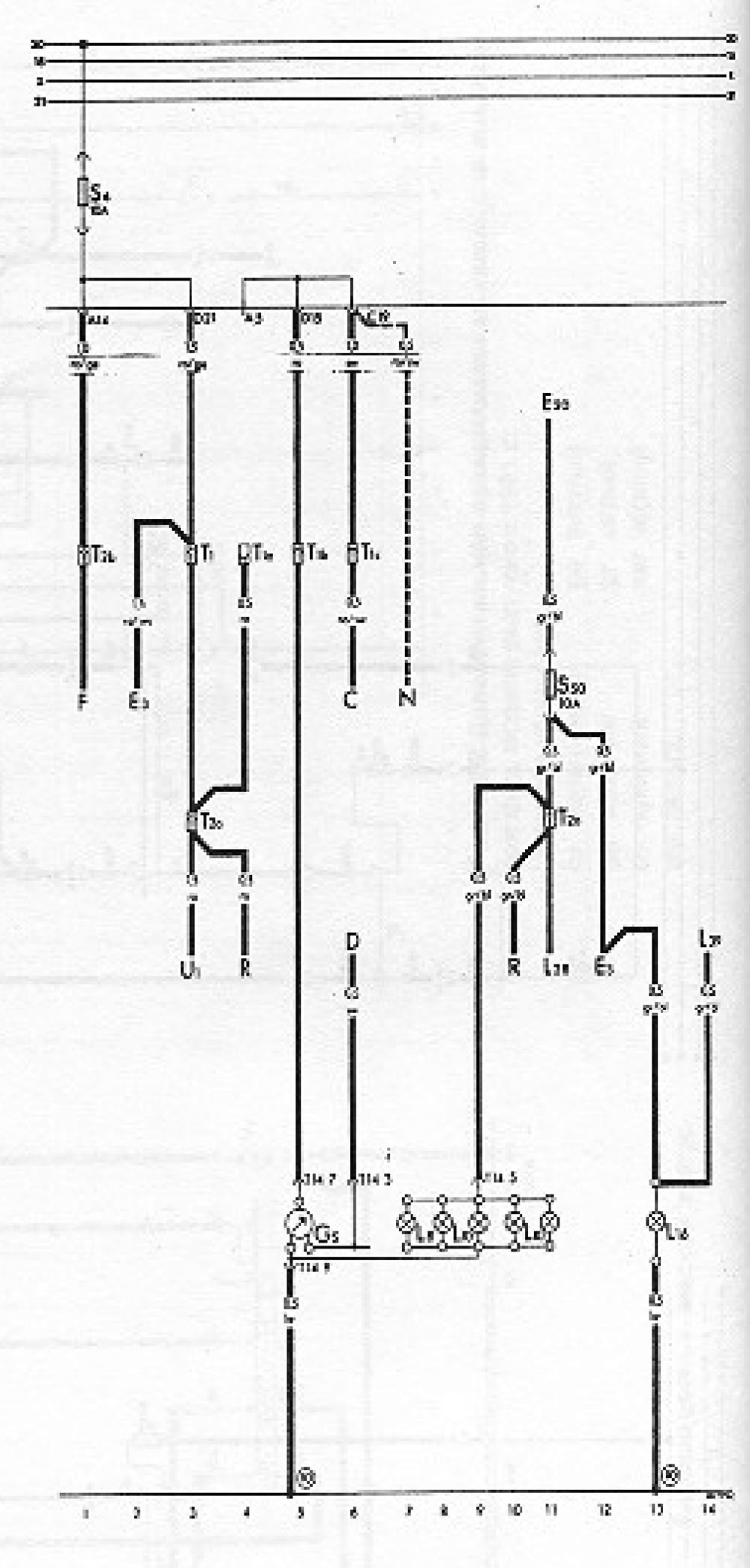
Conventional designations
| Designation | Device | Track number |
| WITH | Generator (for diesel engines only) | 6 |
| D | Ignition/starter switch | 6 |
| EZ | Hazard warning switch | 2, 12 |
| E20 | Instrument/dashboard dimmer | 11 |
| F | Brake light switch | 1 |
| G5 | Tachometer | 5 |
| L8 | Clock backlight lamp | 7 |
| L10 | Instrument panel insert lighting lamp | 8-11 |
| L16 | Control panel illumination lamp, fresh air ventilation | 13 |
| L28 | Cigarette lighter illumination lamp | 11 |
| L39 | Rear window defroster switch illumination lamp | 14 |
| N | Ignition coil (for gasoline engines only) | 7 |
| R | Radio receiver connector | 4, 10 |
| S6 | Fuse in the fuse box | |
| S50 | Fuse on the relay adapter | |
| T1 | Single-pole connector, behind the dashboard | |
| T1a | Single-pole connector, behind the dashboard | |
| T1b | Single-pole connector, behind the dashboard | |
| T1s | Single-pole connector, behind the dashboard | |
| T2a | 2-pin connector, behind the dashboard | |
| T2b | 2-pin connector, behind the dashboard | |
| T14/ | 14-pin connector, behind the dashboard | |
| U1 | Cigarette lighter | 3 |
| 10 | Grounding point, behind the dashboard | |
Color coding
- bl - blue
- br - brown
- ge - yellow
- gn - green
- gr - gray
- ro - red
- sw - black
- ws - white
Visitor comments