
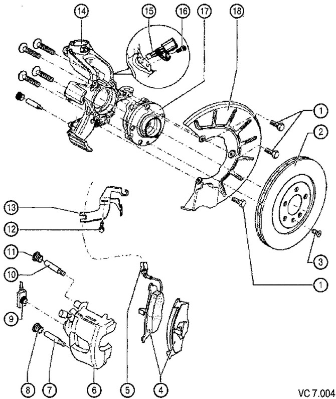
List of parts and assemblies with notes on installation work to Figure VC7.004:
1. Hex head bolt: 10 Nm.
2. Brake disc:
- ventilated, diameter 280 mm;
- thickness 22 mm;
- minimum allowable thickness: 19 mm;
- replace all pads for the corresponding axle;
- To remove, you must first dismantle the brake caliper.
3. Phillips head screw: 4 Nm.
4. Brake pad wear gauge:
- thickness 14 mm (excluding base plate thickness);
- with appropriate wear (threshold: about 4mm) the control lamp on the instrument cluster lights up;
- limit tolerance: 2 mm without back plate;
- replace all pads for the corresponding axle.
5. Brake pad wear sensor connector.
6. Brake caliper:
- It is not necessary to unscrew the brake hose to replace the brake pads.
7. Guide: 30 Nm.
8. Protective cap:
- take off.
9. Brake hose with union and hollow screw 35 Nm.
10. Guide 30 Nm.
11. Protective cap.
12. Bolt.
13. Bracket.
14. Steering knuckle with integrated brake caliper.
15. Speed sensor (ABS):
- before installing the sensor, clean the hole and apply a little plastic refractory grease G 052 112 AZ.
16. Bolt with hexagon socket 8 Nm.
17. Bearing assembly:
- a magnetic ring for the operation of the ABS sensor is built into the bearing.
18. Brake shield, brake caliper FSIII.
Attention: after replacing the brake pads, press the brake pedal hard several times. This is necessary so that the brake pads and the piston of the brake cylinder take their working position.
Visitor comments