



Contents: Checking the axial clearance ↓ Valve sizes ↓ AFT Engine Valve Dimensions ↓ Engine Valve Dimensions 1F ↓ ADZ Engine Valve Dimensions ↓ Identification of camshafts ↓
The elements of the gas distribution mechanism of the AFT engine are shown in Fig. 5.20, and of the 1F and ADZ engines - in Fig. 5.21.
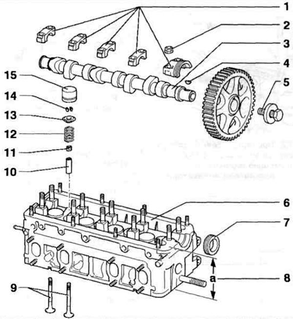
Fig. 5.20. Elements of the AFT engine valve timing mechanism:
1 - Camshaft main caps; 2 - Nut; 3 - Camshaft; 4 - Key; 5 - Bolt; 6 - Cylinder head: 7 - Camshaft oil seal: 8 - Cylinder head repair height; 9 - Valves; 10 - Valve guide bushing; 11 - Valve stem seal; 12 - Valve spring; 13 - Upper spring plate; 14 - Rusks; 15 - Hydraulic compensator.
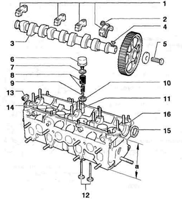
Fig. 5.21. Elements of the gas distribution mechanism of engines 1F, ADZ:
1 - Camshaft main caps; 2 - Nut; 3 - Camshaft; 4 - Key; 5 - Bolt; 6 - Hydraulic compensator; 7 - Upper spring plate: 8 - Valve spring; 9 - Valve stem seal; 10 - Lower spring plate; 11 - Valve guide bushing; 12 - Valves; 13 - Sealing plugs; 14 - Oil can; 15 - Camshaft oil seal; 16 - Cylinder head.
Checking the axial clearance
Checking the axial clearance of the camshaft using an indicator is shown in Fig. 5.22.
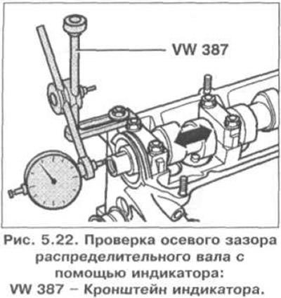
Permissible axial clearance: 0.15 mm.
Valve sizes
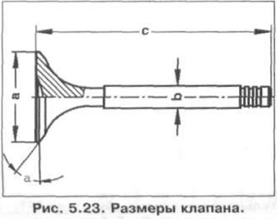
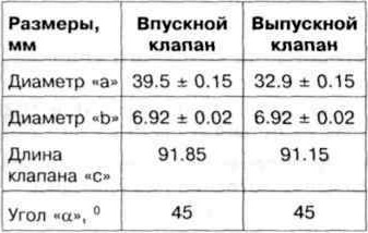
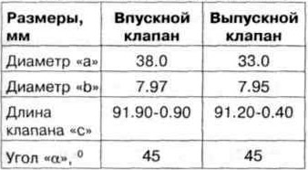
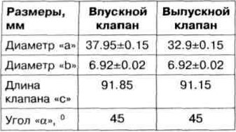
The valve dimensions are shown in Fig. 5.23.
AFT Engine Valve Dimensions
Engine Valve Dimensions 1F
ADZ Engine Valve Dimensions
Identification of camshafts
Main cam diameter: 34 mm.
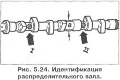
The camshaft identification is stamped between the intake and exhaust cams.
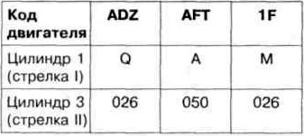
Identification of the camshaft is shown in Fig. 5.24.
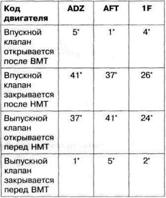
Valve timing with 1 mm valve lift
Visitor comments