
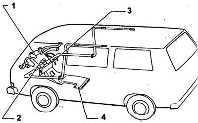
(1) heating and ventilation
(2) fresh air and heating control
(3) control valve
(4) air channel. Built into buses without additional heating system. Subsequent installation in vehicles with an additional heating system is not permitted.
Remove the fresh air and heating control levers and the blower button.
Remove the decorative panel with a screwdriver.
Remove glove box.
Remove the control panel, see "Dismantling and installation of the control panel".
In cars "combi", onboard, vans and with a double cab, a heating control system with three levers is installed, because. there is no damper for ventilation of the passenger compartment. There is no lower fourth lever.
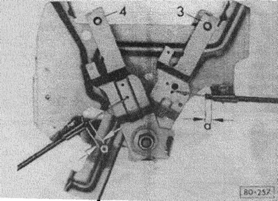
(80-257) the lower arm 4 is connected to a rod with two green marks. The link leads to the flap for the passenger compartment. a = 3 mm.
The lower arm 3 is connected to a link with green and yellow markings. The rod leads to the main shut-off damper.
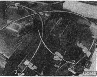
(80-251) 1 - passenger compartment ventilation damper, 2 - main shut-off damper, 3 - windshield and legroom damper.
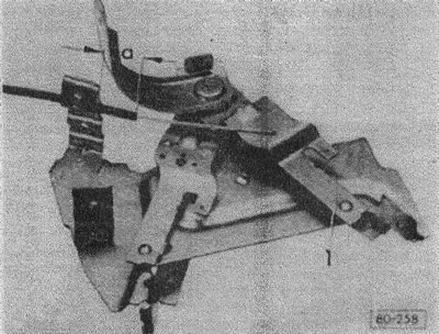
(80-258) the upper arm 1 is connected to the link marked in red. The draft leads to the warm air distributor if the DA6 auxiliary heating system is installed. a = not more than 38 mm.
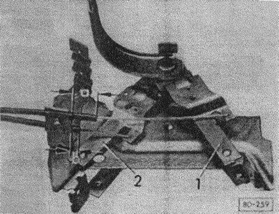
(80-259) the upper arm 2 is connected to the rod, which has a blue and yellow marking. The link leads to the control valve. a = 30 mm, b = 20 mm.
Upper arm 1 is connected to the link marked red. It leads to the windshield defroster and foot warmers.
Install glove box.
Install the control panel.
Install decorative plate.
Slide on the fresh air and heating control levers and the blower button.
Visitor comments