



1. Connect the VAG 1551 fault code reader (V.A.G 1552) and dial "01" "Engine Electronics". The engine should idle. The display should show the following information:

2. Press "08" to select the "Read measured value block" function and confirm by pressing the "Q" key. The following information should appear on the display.

3. Select the desired group. Press "062" to select "Display Group 62" and confirm with "Q". The display should show the following information:

4. Check the specification values of sensor 1 G79 in zone 3: 3-100%. Check the specification values of sensor 2 G185 in zone 4: 3-100%.
The engine control unit calculates the value of the steering angle sensor voltage as a percentage of 5 Volts and displays this percentage (5 Volts equals 100%).
5. Press the accelerator pedal slowly until it is fully depressed and observe the change in the values in fields 3 and 4 of the display. The percentages in both fields should increase equally.
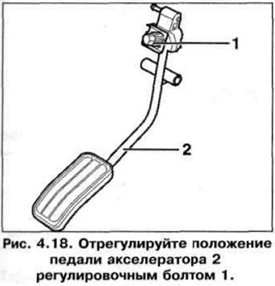
6. If the specified value is not achieved, adjust the position of the accelerator pedal 2 with the adjusting bolt 1 (Fig. 4.18).
7. If the specified value is not reached:
- press "→".
- press "06" to select the "Complete Output" function and confirm by pressing the "Q" button;
- turn off the ignition.
8. If the display does not show the required value, check the supply voltage and sensor wires.
(The original can be seen on the portal: «VWmanual.ru»)
Checking the supply voltage and wires to the control unit
9. Remove the glove box from the driver's side.
10. Disconnect the six-pin wiring connector from the accelerator pedal position sensor.
11. Turn off the ignition.
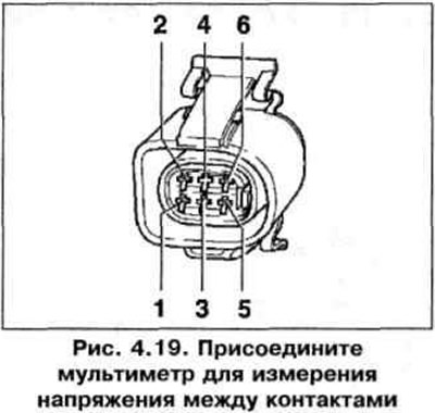
12. Connect a multimeter to measure the voltage between the connector contacts (Fig. 4.19): contact 2 + ground, contact 2 + 3, contact 5 + ground, contact 5 + 4. Specification: minimum 5 V.
12. Turn off the ignition.
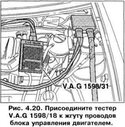
13. If the specified value is not reached: connect the VAG 1598/18 tester to the wiring harness of the engine control unit. The control unit must be disconnected (Fig. 4.20).
14. Check the wire between the tester and the connector for open circuit.
pin 1 + Socket 35, Pin 2 + Socket 73, Pin 3 + Socket 36, Pin 4 + Socket 33, Pin 5 + Socket 72, Pin 6 + Socket 34. Set value: Max. 1.5 Ohm.
15. Additionally, check the wires for a short circuit to the positive pole or to ground.
16. Additionally, check for short circuits between wires.
17. If no faults are found, replace the accelerator pedal position sensor.
Visitor comments