
English Русский
Български
Беларускі
Український
Српски
Hrvatski
Română
Polski
Slovenský
Magyar
  |  Articles  |  Sitemap  |  Contacts  |    |
Car maintenance Ford Car maintenance Hyundai Car maintenance Chevrolet Car maintenance BMW Car maintenance Audi Car maintenance Opel Car maintenance AvtoVAZ
VWmanual.ru


Main   Passat   Golf   Polo   Touareg   Tiguan   Sharan   Transporter   Others  
LT 28 (1975-1991) LT 2D (1996-2003) Beetle (1960-1986) Caddy 3 (2003-2010)

Control cables (VW Lt 2d)

  • Main
  • Volkswagen
  • LT 2D
  • Body
  • Heating system
  • Control cables
            0


Contents: Control cable for the regulating…↓ Windshield defroster flap control…↓ Footwell air flap control cable ↓
The control cables are shown in the figure 9.61.
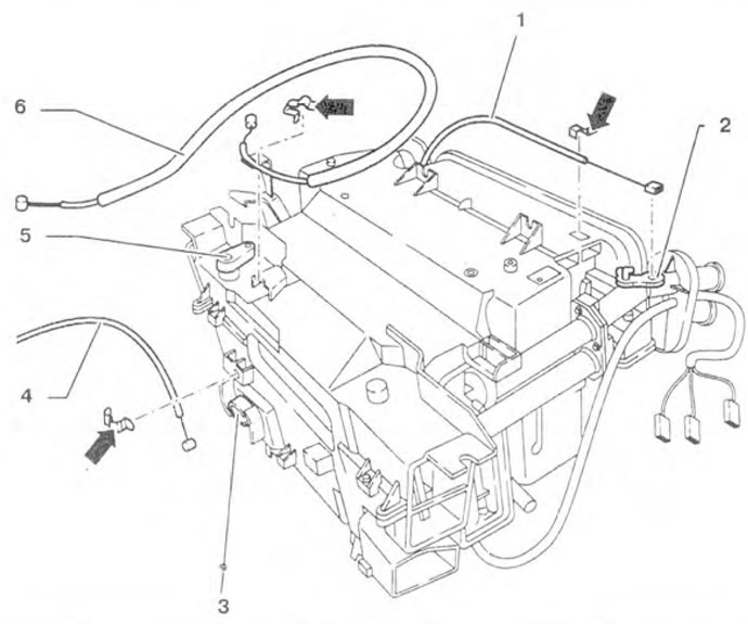
Figure 9.61. Control cables: 1 - Control cable for the regulating valve; 2 - Control valve lever; 3…

Figure 9.61. Control cables: 1 - Control cable for the regulating valve; 2 - Control valve lever; 3 - Footwell air supply flap control lever; 4 - Footwell air supply flap control cable; 5 - Windscreen heater flap lever 6 - Windscreen heater flap control cable.


Control cable for the regulating valve


Removal


1. Remove the heater.

2. Disconnect the retainer 1 (figure 9.62). Move cable 2 upwards (arrow) and unhook it.
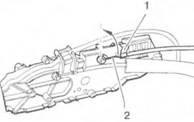
Figure 9.62. Disconnect lock 1. Move cable 2 upward (arrow) and unhook it.

Figure 9.62. Disconnect lock 1. Move cable 2 upward (arrow) and unhook it.


The original information is posted on the resource (VWmanual.ru)


3. Disconnect the clamp 3. Unhook the cable 2 from the lever 1 of the control valve (figure 9.63)
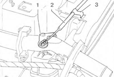
Figure 9.63. Disconnect the retainer. Unhook cable 2 from lever 1 of the control valve.

Figure 9.63. Disconnect the retainer. Unhook cable 2 from lever 1 of the control valve.


Installation


4. Install the cable with the blue mark for the control valve on the hot and fresh air supply control regulator. Sleeve 2 on the cable must go in all the way (arrow) (figure 9.64). Press the lock 1. Turn the temperature control to the extreme position to supply cold air.
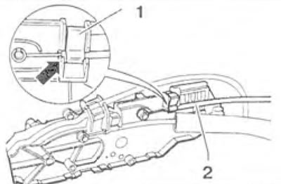
Figure 9.64. Sleeve 2 on the cable should go all the way in (arrow). Press lock 1.

Figure 9.64. Sleeve 2 on the cable should go all the way in (arrow). Press lock 1.


5. Hold lever 1 and attach cable 2 with clamp 3 (figure 9.65). Turn the temperature control to ensure that the "cold air" and "hot air" positions are determined by the control valve.
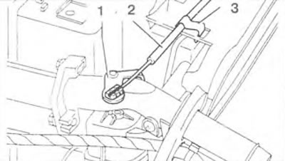

Figure 9.65. Hold lever 1 and attach cable 2 to clamp 3.

Figure 9.65. Hold lever 1 and attach cable 2 to clamp 3.


Windshield defroster flap control cable


Removal


6. Disconnect the retainer 1 (figure 9.66). Move cable 2 upwards (arrow) and unhook it.
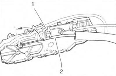
Figure 9.66. Disconnect lock 1. Move cable 2 upward (arrow) and unhook it.

Figure 9.66. Disconnect lock 1. Move cable 2 upward (arrow) and unhook it.


7. Disconnect the retainer 2 (figure 9.67). Move cable 1 counterclockwise (arrow) and unhook it.
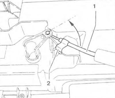
Figure 9.67. Disconnect lock 2. Move cable 1 counterclockwise (arrow) and unhook it.

Figure 9.67. Disconnect lock 2. Move cable 1 counterclockwise (arrow) and unhook it.


Installation


8. Install the cable with the black mark for the defroster flap onto the heated and fresh air control knob. Sleeve 2 on the cable must go in all the way (arrow) (figure 9.68). Press the lock 1.
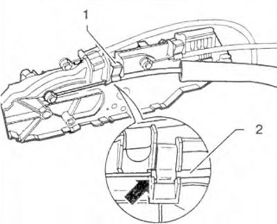
Figure 9.68. Sleeve 2 on the cable should go all the way in (arrow). Press lock 1.

Figure 9.68. Sleeve 2 on the cable should go all the way in (arrow). Press lock 1.


9. Set the air distribution regulator to position 1 (figure 9.69).
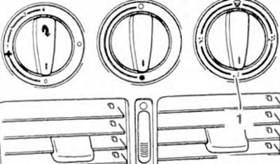
Figure 9.69. Set the air supply distribution regulator to position 1.

Figure 9.69. Set the air supply distribution regulator to position 1.


10. Hold lever 1 (arrow) and attach cable 1 with clamp 2 (figure 9.70).
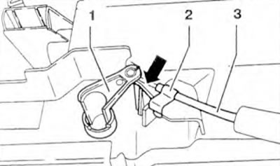
Figure 9.70. Hold lever 1 (arrow) and attach cable 1 to clamp 2.

Figure 9.70. Hold lever 1 (arrow) and attach cable 1 to clamp 2.


11. Turn the air distribution control to ensure that the defroster flap is working.

Footwell air flap control cable


Removal


12. Disconnect the retainer 2 (figure 9.71). Move cable 1 upwards (arrow) and unhook it.
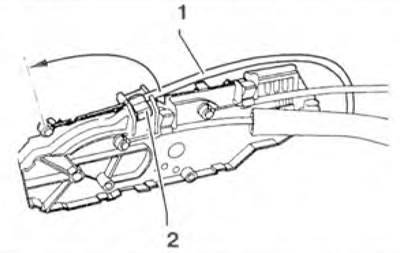
Figure 9.71. Disconnect lock 2. Move cable 1 upward (arrow) and unhook it.

Figure 9.71. Disconnect lock 2. Move cable 1 upward (arrow) and unhook it.


13. Disconnect the lock 1. Move the cable 2 counterclockwise (arrow) and unhook it (figure 9.72).
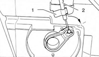
Figure 9.72. Disconnect lock 1. Move cable 2 counterclockwise (arrow) and unhook it.

Figure 9.72. Disconnect lock 1. Move cable 2 counterclockwise (arrow) and unhook it.


Installation


14. Install the cable with the white mark for the footwell air flap onto the heated and fresh air control knob. Sleeve 1 on the cable must go in as far as it will go (arrow) (figure 9.73). Press the lock 2.
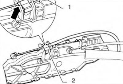
Figure 9.73. Sleeve 1 on the cable should go all the way in (arrow). Press lock 2.

Figure 9.73. Sleeve 1 on the cable should go all the way in (arrow). Press lock 2.


15. Set the air distribution regulator to position 1 (figure 9.74).

16. Press lever 3 until it stops and hold it (arrow) (figure 9.75). Insert the end of the cable winding into lever 3 and tighten sleeve 2 with clamp 1.
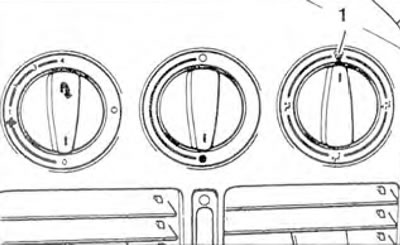
Figure 9.74. Set the air distribution regulator to position 1.
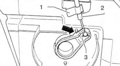
Figure 9.74. Set the air distribution regulator to position 1.


Figure 9.75. Press lever 3 until it stops and hold it (arrow). Insert the end of the cable winding…

Figure 9.75. Press lever 3 until it stops and hold it (arrow). Insert the end of the cable winding into lever 3 and tighten sleeve 2 with lock 1.


17. Turn the air distribution control to ensure that the footwell air flap is operating.

This article is available at russian, bulgarian, belarusian, ukrainian, serbian, croatian, romanian, polish, slovak, hungarian
The text has been checked: Kolesnikov Artem

Share information:

Previous articles
Disassembling and assembling the heater
Removal and installation the heater
Regulators for controlling the supply of heated and fresh air
Elements of the heating system
Next articles
Fan housing
Heater radiator
Heating system error codes
Air conditioner components


Similar articles from other manuals for VW cars:
Removal and installation control cables — parts and components Passat B6 (2005-2010)
Removal and installation heating and ventilation system control… Golf 4 (1997-2004)
Location of switches, instruments and control levers Polo 3 (1995-2003)
Remote control of locks Touareg 1 (2002-2006)
Signal and control lamps Tiguan 1 (2007-2015)
Electronic control unit — general information Sharan 1 (1995-2000)
Heater control cables — removal and installation Transporter T4 (1990-2003)
Link to this page in different formats


Visitor comments


No comments yet


How much will 42 + 24 =


Caddy 3 
  • General information
  • User manual
  • Daily care
  • Maintenance
  • Petrol engines 1.4 l
  • Engine repair
  • Cooling and lubrication system
  • Power and exhaust system
  • Petrol engines 1.6 l
  • Engine repair
  • Cooling and lubrication system
  • Power and exhaust system
  • Diesel engines
  • Engine repair
  • Cooling and lubrication system
  • Power and exhaust system
  • Transmission
  • Mechanical gearbox 0AH
  • Mechanical gearbox 0A4
  • Drive shafts
  • Chassis
  • Car suspension
  • Steering
  • Brake system
  • Body and wiring diagrams
  • Interior and exterior
  • Electrical circuits
Beetle 
  • General information
  • Maintenance
  • Power unit
  • Engine repair
  • Cooling and lubrication system
  • Supply system
  • Exhaust system
  • Transmission
  • Clutch
  • Car gearbox
  • Chassis
  • Front suspension
  • Rear suspension
  • Steering
  • Brake system
  • Wheels and tires
  • Body
  • Exterior
  • Electrical equipment
  • Equipment and devices
  • Power devices
  • Electrical circuits
LT 2D 
  • General information
  • User manual
  • Maintenance
  • Power unit
  • Petrol engines 2.3 l
  • Diesel engines 2.5 l
  • Diesel engines 2.8 l
  • Injection system (diesel 2.8 l)
  • Transmission
  • Clutch
  • Manual gearbox
  • Differential
  • Chassis
  • Car suspension
  • Steering system
  • Brake system
  • Body
  • Body elements
  • Heating system
  • Electrical equipment
  • Equipment and devices
  • Electrical circuits
LT 28 
  • General information
  • Maintenance
  • Power unit
  • Petrol engines 2.0L
  • Petrol engines 2.4L
  • Diesel engines
  • Cooling and heating
  • Fuel and exhaust system
  • Ignition system
  • Transmission
  • Clutch
  • Car gearbox
  • Cardan shaft
  • Rear axle
  • Chassis
  • Brake system
  • Car suspension
  • Steering system
  • Body
  • Body elements
  • Doors, locks and windows
  • Electrical equipment
  • Power devices
  • Equipment and devices
  • Electrical circuits
VWmanual.ru © 2016-2026 | Mobile version | News and articles | Sitemap: EN BG BY UA RS HR RO PL SK HU | Write message | Site search
Passat B2 • Passat B3 • Passat B4 • Passat B5 • Passat B6 • Golf 1, diesel • Golf 1, petrol • Golf 2, petrol • Golf 2 • Golf 3 • Golf 4 • Golf 5 • Polo 3 • Polo 4 • Touareg 1 • Tiguan 1 • Sharan 1 • Transporter T3 • Transporter T4 • LT 28 • LT 2D • Beetle • Caddy 3 •
Our website uses cookies to ensure functionality and convenience.