



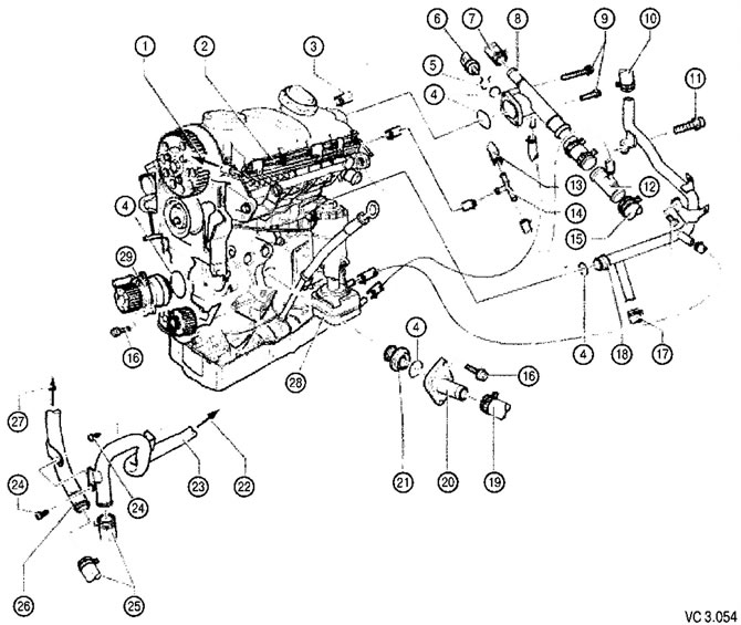
List of units and parts of the cooling system installed on the engine, with technological notes on repairs to Figure VC3.054:
1. To the upper fitting of the expansion tank.
2. Coolant supply pipe, upper:
- screwed to the valve cover.
3. To the bypass valve:
- connection diagram of cooling system hoses.
4. Sealing ring:
- replace with a new one during assembly.
5. Fixing bracket:
- check the reliability of the fastening.
6. Coolant temperature sensor (G62) with a sensor for the coolant temperature gauge (G2).
7. To the exhaust gas recirculation system cooling heat exchanger:
- connection diagram of cooling system hoses.
8. Coolant collector,
9. Manifold mounting screws: 10 Nm.
10. To the heat exchanger.
11. Screw: 40 Nm.
12. Tee.
13. To the bypass valve.
14. Tee.
15. To the top of the radiator.
16. Screw: 15 Nm.
17. To the lower nipple of the expansion tank.
18. Coolant return manifold.
19. To the bottom of the radiator,
20. Thermostat pipe.
21. Thermostat:
- check by heating in a vessel with water:
- start of opening: approximately 85°C,
- fully open: approximately 105°C,
- the height of the plate lift is not less than 7 mm.
22. To the heat exchanger.
23. Rear coolant pipe.
24. Screw: 10 Nm.
25. To the additional heater.
26. Coolant pipe.
27. To the exhaust gas recirculation radiator.
28. Oil radiator.
29. Coolant pump:
- check the rotor for jamming.
Visitor comments