English Русский
Български
Беларускі
Український
Српски
Hrvatski
Română
Polski
Slovenský
Magyar
  |  Articles  |  Sitemap  |  Contacts  |    |
Car maintenance Ford Car maintenance Hyundai Car maintenance Chevrolet Car maintenance BMW Car maintenance Audi Car maintenance Opel Car maintenance AvtoVAZ
VWmanual.ru


Main   Passat   Golf   Polo   Touareg   Tiguan   Sharan   Transporter   Others  
Polo 3 (1995-2003) Polo 4 (2001-2009)

Tripod type axle shafts (VW Polo 3)

  • Main
  • Polo
  • Polo 3
  • Chassis
  • Front suspension
  • Tripod type axle shafts
            0


Contents: Disassembly ↓ Assembly ↓
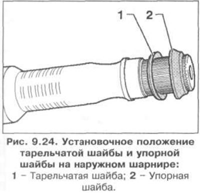
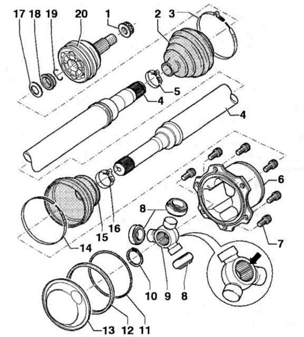
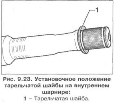
The axle shaft with tri-pod joints is shown in Fig. 9.22. The installation position of the disk washer on the inner joint is shown in Fig. 9.23, the installation position of the disk washer and thrust washer on the outer joint is shown in Fig. 9.24.

Fig. 9.22. Half shaft with tripod type joints:

Fig. 9.22. Half shaft with tripod type joints:
1 - Nut; 2 - CV joint boot; 3, 5, 14, 16 - Clamps; 4 - Half shaft; 6 - Hinge housing; 7 - Bolt; 8 - Rollers; 9 - Three-spined; 10, 19 - Retaining rings; 11, 12 - Seals; 13 - Lid; 15-Boot cover for the "Tripod" type hinge; 17 - Plate washer; 18 - Thrust washer; 20 - Outer CV joint.

1 - Nut; 2 - CV joint boot; 3, 5, 14, 16 - Clamps; 4 - Half shaft; 6 - Hinge housing; 7 - Bolt; 8 -…


1 - Nut; 2 - CV joint boot; 3, 5, 14, 16 - Clamps; 4 - Half shaft; 6 - Hinge housing; 7 - Bolt; 8 -…


Disassembly


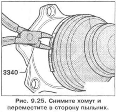
1. Remove the clamp and move the boot to the side (Fig. 9.25).

1. Remove the clamp and move the boot to the side (Fig. 9.25).


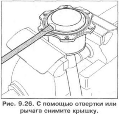
2. Using a screwdriver or lever, remove the cover (Fig. 9.26).

2. Using a screwdriver or lever, remove the cover (Fig. 9.26).


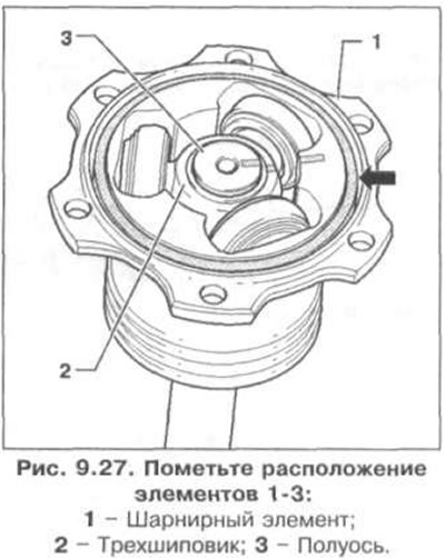
3. Mark the location of elements 1-3 (Fig. 9.27). Otherwise, noise may occur during the ride. Remove the rubber ring (arrow) from the groove.
3. Mark the location of elements 1-3 (Fig. 9.27). Otherwise, noise may occur during the ride.…


4. Hold the joint and remove the axle shaft. Make sure the rollers do not slip off the three-pin.


5. While holding the joint and axle shaft horizontally, use your other hand to slowly move the joint back.

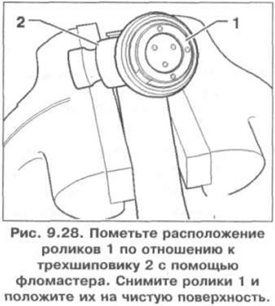
6. Mark the position of rollers 1 in relation to the three-pin 2 using a felt-tip pen (Fig. 9.28). Remove rollers 1 and place them on a clean surface.
6. Mark the position of rollers 1 in relation to the three-pin 2 using a felt-tip pen (Fig. 9.28).…


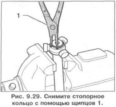
7. Remove the retaining ring using pliers 1 (Fig. 9.29).

7. Remove the retaining ring using pliers 1 (Fig. 9.29).


8. Install the axle shaft in the press.

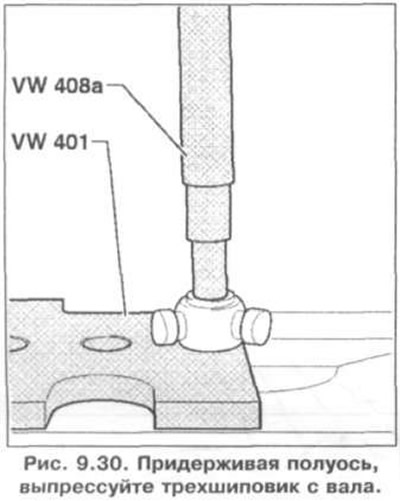
9. Holding the axle shaft, press the three-pin nut out of the shaft (Fig. 9.30).

9. Holding the axle shaft, press the three-pin nut out of the shaft (Fig. 9.30).


10. Remove the joint together with the boot from the axle shaft.

Assembly


11. Place the boot clamps on the axle shaft.

12. Place the dust boots on the axle shaft.

13. Install the hinge element on the axle shaft.

Installing a three-spike


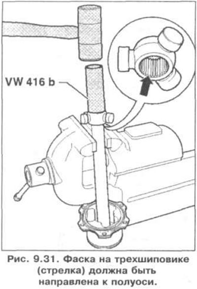
14. The chamfer on the three-spike (arrow) should be directed towards the axle shaft (to facilitate assembly) (Fig. 9.31).

14. The chamfer on the three-spike (arrow) should be directed towards the axle shaft (to facilitate…


15. Install the three-stud onto the axle shaft according to the previously made marks until it stops.

16. Install the retaining ring.

17. Install the rollers on the three-spike wheel according to the marks made earlier

18. Install the hinge element onto the three-pin.

19. Remove the axle shaft from the vice.

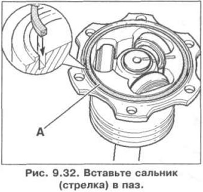
20. Insert the seal (arrow) into the groove (Fig. 9.32).

20. Insert the seal (arrow) into the groove (Fig. 9.32).


21. Apply 90 grams of grease from the repair kit into the inside of the Tripod joint and 90 grams of grease from the repair kit into the back of the Tripod joint.

22. Install the anthers.

23. Install the large clamp using pliers (Fig. 9.25).

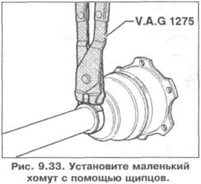
24. Install the small clamp (Fig. 9.33).

24. Install the small clamp (Fig. 9.33).

This article is available at russian, bulgarian, belarusian, ukrainian, serbian, croatian, romanian, polish, slovak, hungarian
The text has been checked: Kolesnikov Artem

Share information:

Previous articles
Constant velocity joint axle shafts
Shock absorber strut
Steering knuckle
Removal and installation the subframe
Removal and installation the lower arm
Removal, installation and inspection of the ball joint
Next articles
Checking the inner CV joint
Checking the outer CV joint
Wheel alignment angles
Front wheel camber adjustment
Front wheel alignment adjustment


Similar articles from other manuals for VW cars:
Front axle design Passat B3 (1988-1993)
Troubleshooting axle shafts Golf 1 (1974-1984, diesel)
Checking the oil level in the main gear of the front axle Touareg 1 (2002-2006)
Removal and installation of the drive shaft with an internal… Tiguan 1 (2007-2015)
Wheel Drive Shafts — Design Description Sharan 1 (1995-2000)
Bottom protection and preservation of axle shafts Transporter T4 (1990-2003)
Removal and installation of axle shafts, joints and their… Beetle (1960-1986)
Link to this page in different formats


Visitor comments


No comments yet


How much will 32 + 38 =


Polo 4 
  • General information
  • User manual
  • Maintenance
  • Power unit
  • Engine repair
  • Cooling and lubrication system
  • Control system
  • Injection system (diesel)
  • Supply system
  • Exhaust system
  • Chassis
  • Front suspension
  • Rear suspension
  • Steering
  • Wheels and tires
  • Brake system
  • Body
  • Interior
  • Exterior
  • Electrical equipment
  • Equipment and devices
  • Wiper system
  • Lighting system
  • Electrical circuits
Polo 3 
  • General information
  • User manual
  • Maintenance
  • Power unit
  • Petrol engines 1.4 and 1.6
  • Petrol engines 1.4 (V16)
  • Petrol engines 1.6 and 1.8
  • Diesel engines 1.7 and 1.9
  • Diesel engines 1.9 D and TD
  • Transmission
  • Mechanical gearbox 085
  • Mechanical gearbox 020/02K
  • Chassis
  • Front suspension
  • Rear suspension
  • Steering
  • Brake system
  • Body
  • Exterior
  • Interior
  • Electrical equipment
  • Equipment and instruments (until 2000)
  • Equipment and instruments (after 2000)
  • Electrical circuits
  • Wiring diagrams (petrol)
  • Wiring diagrams (diesel)
VWmanual.ru © 2016-2026 | Mobile version | News and articles | Sitemap: EN BG BY UA RS HR RO PL SK HU | Write message | Site search
Passat B2 • Passat B3 • Passat B4 • Passat B5 • Passat B6 • Golf 1, diesel • Golf 1, petrol • Golf 2, petrol • Golf 2 • Golf 3 • Golf 4 • Golf 5 • Polo 3 • Polo 4 • Touareg 1 • Tiguan 1 • Sharan 1 • Transporter T3 • Transporter T4 • LT 28 • LT 2D • Beetle • Caddy 3 •
Our website uses cookies to ensure functionality and convenience.