
At the bottom of the diagram there is a coordinate ruler, since, unlike the usual circuit diagrams, Volkswagen car diagrams are arranged linearly, along the main lines (chains) power supply and information data buses.
The conductors in the diagrams are indicated by the color of the insulation by the size of the cross section of the wire.
Example 1:
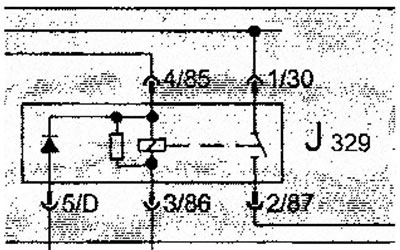
Here is a fragment of the image of the switching unit and the relay included in it (J329 - Power supply relay for power supply 15, in the electronics box, in the engine compartment on the left). The diagram shows that the relay connector has male contacts, and the main unit board connector has female contacts.
All designations printed on the diagram can be deciphered according to the list of electrical equipment elements given below. This list contains the designations and names of all the elements depicted in the diagrams placed in this manual.
Example 2:
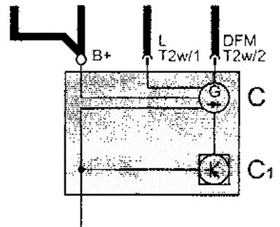
Here is a generator (WITH) with integrated electronic voltage regulator (C1).
Wire to terminal (B+) fastened with a nut, and the wires (L) And (DFM) connected to contacts (1) And (2) electrical connector (T2w).
Example 3:
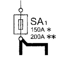
In this example, fuse SA1 is shown with a rating of 150A or 200A, depending on the vehicle configuration.
In addition, the list of electrical equipment items in alphabetical order shows not only connectors, but also all intermediate wire connections and connections with «weight».
Example 4:
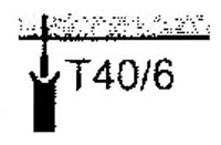
This is how the contact is designated and depicted (№b) connector (T40).
Example 5:
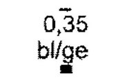
This is the designation of a wire with a cross section of 0.35 square mm, the main color of the insulation is blue, the secondary color of the insulation is yellow.
Insulation color designation on diagrams
| WS | = white |
| SW | = black |
| RO | = red |
| BR | = brown |
| GN | = green |
| BL | = blue |
| GR | = gray |
| Ii | = purple |
| GE | = yellow |
| OR | = orange |
| RS | = pink |
Visitor comments