
English Русский
Български
Беларускі
Український
Српски
Hrvatski
Română
Polski
Slovenský
Magyar
  |  Articles  |  Sitemap  |  Contacts  |    |
Car maintenance Ford Car maintenance Hyundai Car maintenance Chevrolet Car maintenance BMW Car maintenance Audi Car maintenance Opel Car maintenance AvtoVAZ
VWmanual.ru


Main   Passat   Golf   Polo   Touareg   Tiguan   Sharan   Transporter   Others  
Polo 3 (1995-2003) Polo 4 (2001-2009)

Removal and installation the instrument panel (since 10.99) (VW Polo 3)

  • Main
  • Polo
  • Polo 3
  • Body
  • Interior
  • Removal and installation the instrument panel (since 10.99)
            0


Contents: Removal ↓ Installation ↓

Removal


1. Disconnect the negative cable from the battery.

2. Remove the center console.

3. Remove the glove box from the driver's side.

4. Remove the driver's airbag.

5. Remove the glove box.

6. Unscrew screw 1 and remove the upper part of the instrument panel visor 2 in the direction of the arrow (fig. 13.53).

[The original can be found at: VWMANUAL.ru]
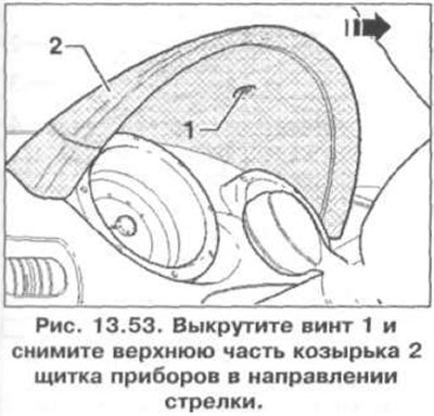
6. Unscrew screw 1 and remove the upper part of the instrument panel visor 2 in the direction of…


7. Unscrew the three screws (arrows) and remove the lower part of the instrument panel visor 1 (fig. 13.54).
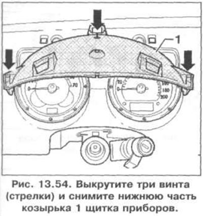
7. Unscrew the three screws (arrows) and remove the lower part of the instrument panel visor 1…


8. Unscrew the two screws (arrows) and remove the instrument panel (fig. 13.55). Disconnect the wiring connector from the instrument cluster.
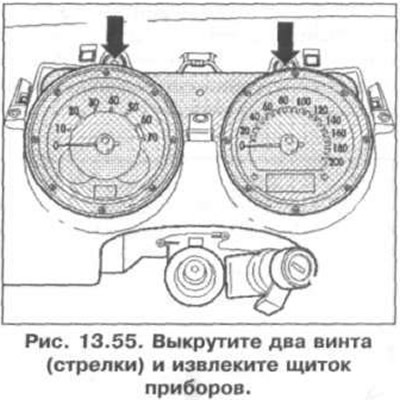
8. Unscrew the two screws (arrows) and remove the instrument panel (fig. 13.55). Disconnect the…


9. Unscrew the nuts (arrows) (fig. 13.56).
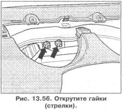


9. Unscrew the nuts (arrows) (fig. 13.56).


10. Press the light switch handle (arrow), turn it clockwise, and remove it (fig. 13.57).
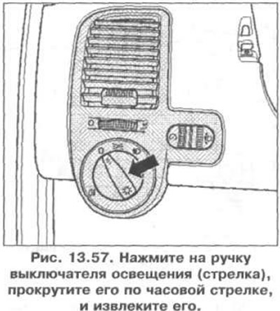
10. Press the light switch handle (arrow), turn it clockwise, and remove it (fig. 13.57).


11. Unscrew the bolt (arrow) and remove the deflector 1 from the driver's side (fig. 13.58). Disconnect the wiring connector from the headlight range adjuster 2.
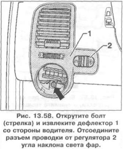
11. Unscrew the bolt (arrow) and remove the deflector 1 from the driver's side (fig. 13.58).…


12. Unscrew screws 1 and 2 and cut the clamps (arrows) (fig. 13.59).
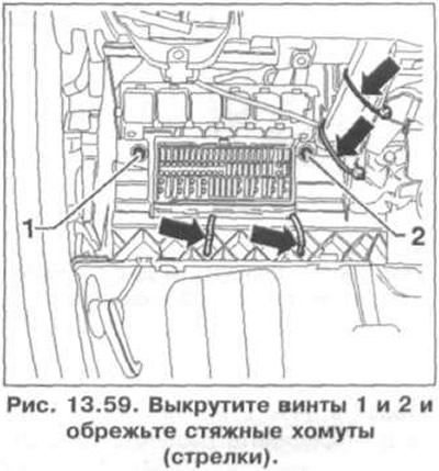

12. Unscrew screws 1 and 2 and cut the clamps (arrows) (fig. 13.59).


13. Unscrew bolts 1 on both sides (fig. 13.60).
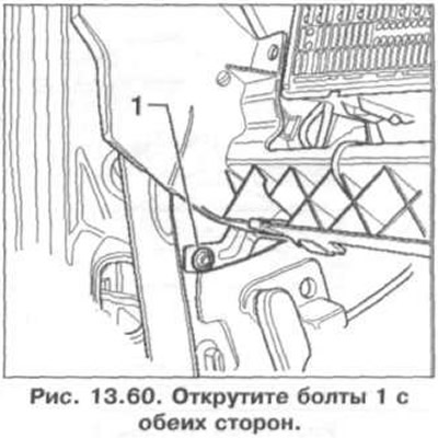
13. Unscrew bolts 1 on both sides (fig. 13.60).


14. Remove plugs 1 and unscrew bolts 2 on both sides (fig. 13.61).
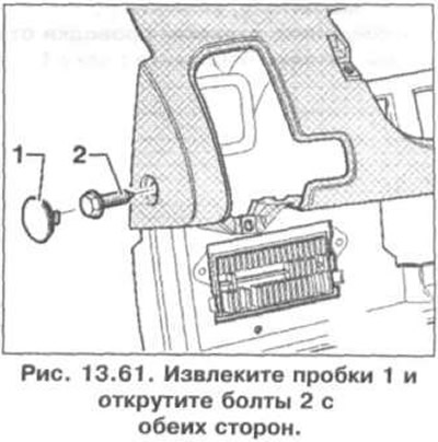
14. Remove plugs 1 and unscrew bolts 2 on both sides (fig. 13.61).


15. Remove the two screws (arrows) and remove the cover in the driver's side footwell (fig. 13.62).
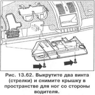
15. Remove the two screws (arrows) and remove the cover in the driver's side footwell (fig. 13.62).


16. Unscrew two screws 1, unscrew nut 2 and remove bracket 3 (fig. 13.63).
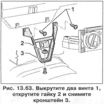
16. Unscrew two screws 1, unscrew nut 2 and remove bracket 3 (fig. 13.63).


17. Insert the T10057 tools into the slots in the radio, remove it and disconnect the wiring connectors from the radio (fig. 13.64). Remove shelf 1.

17. Insert the T10057 tools into the slots in the radio, remove it and disconnect the wiring…


18. Unscrew the three screws (arrows) and remove the central deflector (fig. 13.65). Disconnect the wiring connector from the hazard warning light switch.
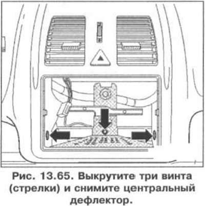
18. Unscrew the three screws (arrows) and remove the central deflector (fig. 13.65). Disconnect the…


19. Remove the two screws (arrows) (fig. 13.66).
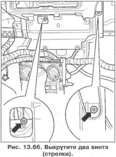
19. Remove the two screws (arrows) (fig. 13.66).


20. Remove the rubber seal 1 and unhook the cover 2 of the water drain (arrows) (fig. 13.67).
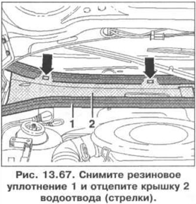
20. Remove the rubber seal 1 and unhook the cover 2 of the water drain (arrows) (fig. 13.67).


21. Unhook the housing 1 and remove the dust filter 2 (fig. 13.68). Unscrew nuts 3 and remove dust filter housing 4.
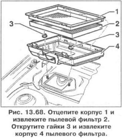
21. Unhook the housing 1 and remove the dust filter 2 (fig. 13.68). Unscrew nuts 3 and remove dust…


22. Unscrew the four bolts (arrows) (fig. 13.69).
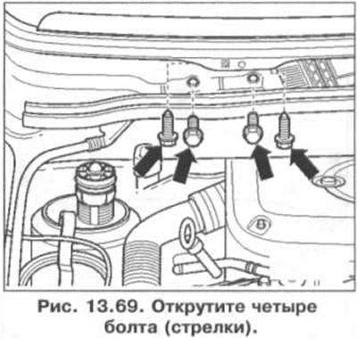
22. Unscrew the four bolts (arrows) (fig. 13.69).


23. Remove the instrument panel (fig. 13.70).
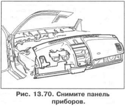
23. Remove the instrument panel (fig. 13.70).


Installation


24. Installation is carried out in the reverse order of removal.

This article is available at russian, bulgarian, belarusian, ukrainian, serbian, croatian, romanian, polish, slovak, hungarian
The text has been checked: Kolesnikov Artem

Share information:

Previous articles
Removal and installation the instrument panel (up to 09.99)
Removal and installation interior door trim
Driver's storage compartment
The location of some elements inside the cabin
Next articles


Similar articles from other manuals for VW cars:
Instrument panel Passat B3 (1988-1993)
Upper instrument panel trim driver side (Golf) Golf 5 (2003-2008)
Black and white display in the instrument cluster Touareg 1 (2002-2006)
Front support panel Tiguan 1 (2007-2015)
Instrument visor (dashboard) on the instrument panel Transporter T4 (1990-2003)
Instrument panel — removal and installation Beetle (1960-1986)
Link to this page in different formats


Visitor comments


No comments yet


How much will 22 + 30 =


Polo 4 
  • General information
  • User manual
  • Maintenance
  • Power unit
  • Engine repair
  • Cooling and lubrication system
  • Control system
  • Injection system (diesel)
  • Supply system
  • Exhaust system
  • Chassis
  • Front suspension
  • Rear suspension
  • Steering
  • Wheels and tires
  • Brake system
  • Body
  • Interior
  • Exterior
  • Electrical equipment
  • Equipment and devices
  • Wiper system
  • Lighting system
  • Electrical circuits
Polo 3 
  • General information
  • User manual
  • Maintenance
  • Power unit
  • Petrol engines 1.4 and 1.6
  • Petrol engines 1.4 (V16)
  • Petrol engines 1.6 and 1.8
  • Diesel engines 1.7 and 1.9
  • Diesel engines 1.9 D and TD
  • Transmission
  • Mechanical gearbox 085
  • Mechanical gearbox 020/02K
  • Chassis
  • Front suspension
  • Rear suspension
  • Steering
  • Brake system
  • Body
  • Exterior
  • Interior
  • Electrical equipment
  • Equipment and instruments (until 2000)
  • Equipment and instruments (after 2000)
  • Electrical circuits
  • Wiring diagrams (petrol)
  • Wiring diagrams (diesel)
VWmanual.ru © 2016-2026 | Mobile version | News and articles | Sitemap: EN BG BY UA RS HR RO PL SK HU | Write message | Site search
Passat B2 • Passat B3 • Passat B4 • Passat B5 • Passat B6 • Golf 1, diesel • Golf 1, petrol • Golf 2, petrol • Golf 2 • Golf 3 • Golf 4 • Golf 5 • Polo 3 • Polo 4 • Touareg 1 • Tiguan 1 • Sharan 1 • Transporter T3 • Transporter T4 • LT 28 • LT 2D • Beetle • Caddy 3 •
Our website uses cookies to ensure functionality and convenience.