
Removing
1. Disconnect the negative cable from the battery.
2. Remove the center console.
3. Remove a ware box from outside the driver.
4. Remove the driver's airbag.
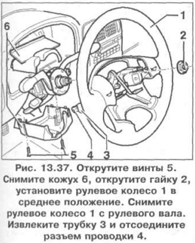
5. Remove screws 5 (pic. 13.37). Remove the casing 6. unscrew the nut 2, set the steering wheel 1 to the middle position (wheels are in straight ahead position). Remove the steering wheel 1 from the steering shaft. Remove tube 3 and disconnect wiring connector 4.
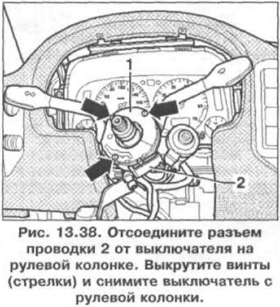
6. Disconnect the wiring connector 2 from the switch on the steering column (pic. 13.38). Remove the screws (arrows) and remove the switch from the steering column.
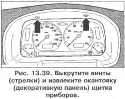
7. Remove the screws (arrows) and remove the edging (decorative panel) instrument panel (pic. 13.39).
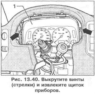
8. Remove the screws (arrows) and remove the instrument panel (pic. 13.40). Disconnect the wiring connector.
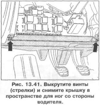
9. Remove the screws (arrows) and remove the footwell cover on the driver's side (pic. 13.41).
10. Loosen nuts 2 (pic. 13.42). Nuts 2 are located inside the steering column bracket. They can be seen between the steering column bracket 3 and the bulkhead of the engine compartment. When installing the nuts 2 must be screwed onto the studs 1 through the opening (arrow) in bracket 3.

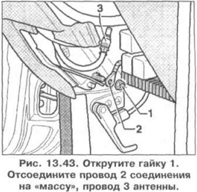
11. Unscrew nut 1 (pic. 13.43). Disconnect wire 2 connections on «mass», wire 3 antennas.
12. Disconnect instrument panel wiring connectors from relay panel.
13. Disconnect the wiring connectors from the immobilizer control unit and the heater fan.
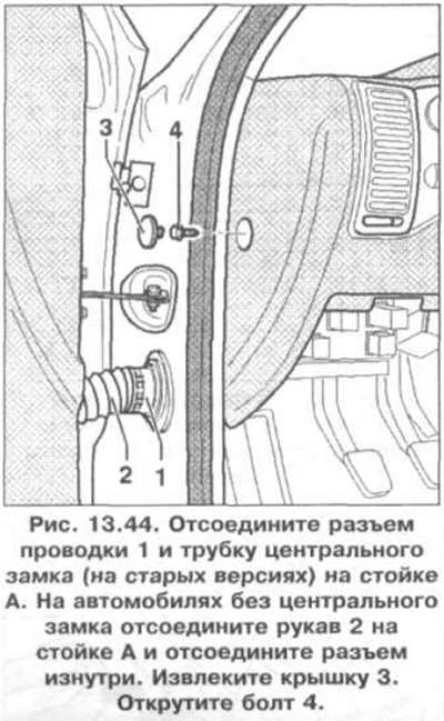
14. Disconnect the wiring connector 1 and the tube of the central lock (on older versions) on the A-pillar (pic. 13.44). On vehicles without central locking, disconnect sleeve 2 on the A-pillar and disconnect the connector from the inside. Remove cover 3. Unscrew bolt 4.
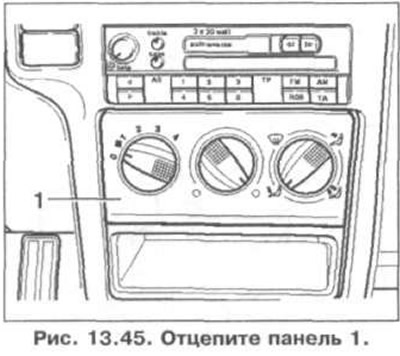
15. Unhook panel 1 (pic. 13.45).
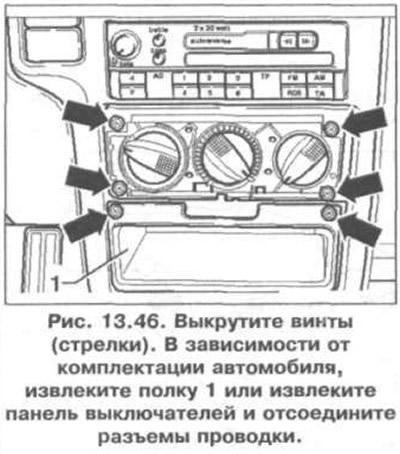
16. Remove the screws (arrows) (pic. 13.46). Depending on the vehicle equipment, remove shelf 1 or remove the switch panel (heated seats and power windows) and disconnect the wiring connectors.
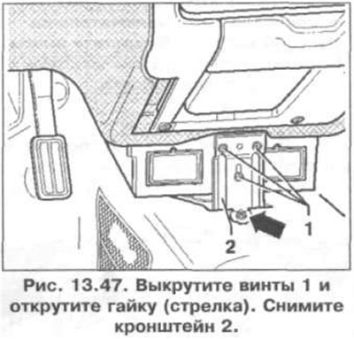
17. Remove screws 1 and unscrew the nut (arrow) (pic. 13.47). Remove bracket 2.
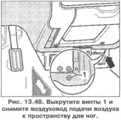
18. Remove screws 1 and remove the air supply duct to the footwell (pic. 13.48).
19. Disconnect the wiring connector from the airbag control unit.
20. Remove the glove box on the passenger side.
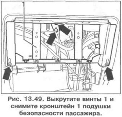
21. Remove the screws 1 and remove the passenger airbag bracket 1 (pic. 13.49).
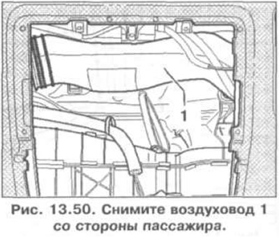
22. Remove the air duct 1 on the passenger side (pic. 13.50).
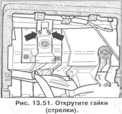
23. Loosen nuts (arrows) (pic. 13.51).
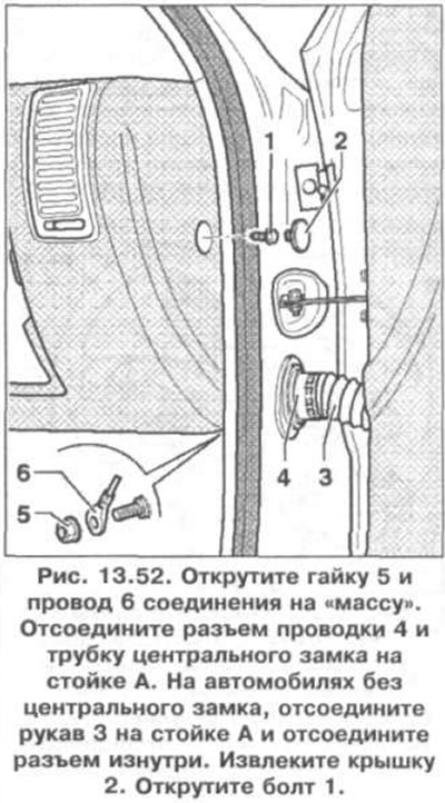
24. Unscrew nut 5 and wire 6 of the connection on «mass» (pic. 13.52). Disconnect the wiring connector 4 and the tube of the central lock (on older versions) on the A-pillar. On vehicles without central locking, disconnect sleeve 3 on the A-pillar and disconnect the connector from the inside. Remove cover 2. Unscrew bolt 1.
25. Remove the instrument panel.
Installation
26. Installation is carried out in the reverse order of removal.
Visitor comments